Here's how to convert GE Rangr radios for 'frequency agile' use on 10, 6, and 2 meters, or for 440 Mhz. Links to some service manuals are included. Review these instructions before starting. Don't attempt it if you don't feel that you can accomplish it satisfactorily or safely.
The conversion is disciplined, but not difficult. Once done, you'll have a 100 watt, high quality FM radio of which you can be proud.
a) General Conversion Information - Schematic
If you are converting the Rangr model for use on the ham bands, you need the proper 'split'. Please review these instructions before you start. E-mail me with questions.
The external M/P replaces the frequency selection functions of the Rangr's internal M/P. The leads connecting to the Rangr's frequency synthesizer will be 'disconnected. In turn, the external M/P 'channels' the PLL for receive and transmit, ana seamlessly manages the CTCSS and wideband functions.
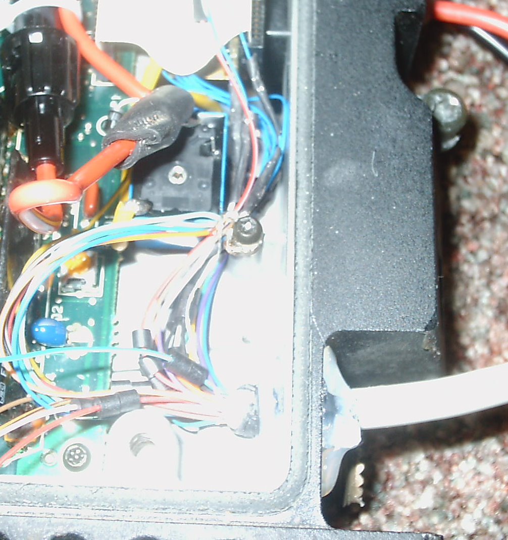
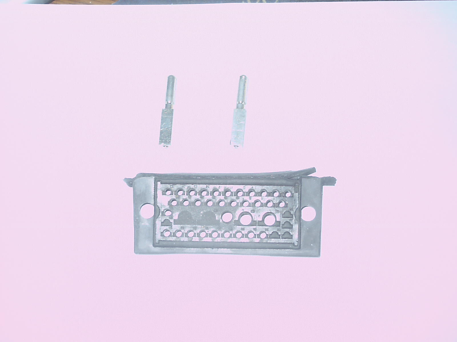
The conversion involves drilling one hole in the front the Rangr, making the interface connections with a 25 pair shielded (DB-25) cable and with separate power and ground leads fed through the conventional connector mounting.
Note: Even though this conversion will not affect the Rangr's 'spectral purity', the FCC's 'type acceptance' was voided when the radio was modified to accept the frequency agile controller so it can never again be used to transmit on non-amateur frequencies.
The fused low current 12 VDC lead (say, from your car's ignition switch) that runs to pin 19 on P / J-801 can be brought to the control head and activated by a switch on the volume control. This switched 12 VDC source will also be needed for the new M/P board. If this powering technique is used, then no other leads within P / J-801 or the DB-25 cable are required.
Another option is using a small remote power relay in the Rangr, permitting the removal of the control head when not in use. Placing a ground on pin 17 of the DB-25 cable will operate the relay and provide power to both the Rangr (on J-801, pin 19) and to the Control Head (on pin 3 of the DB-25 cable). These radios draw considerable current on receive and can easily render a car - whose battery is not charging - incapable of starting in short order.
Drill a small hole in the front of the Rangr just above the coax connector, gradually enlarging it. You need a hole large enough to insert the DB-25 cable into the top side of the Rangr (where the Control Board is located).
On J-801, pins 18 and 20, connect a pair of twisted 30 gauge wires (10 inches after twisting) for the speaker connection. Then, make the following leads 8 inches long. They will be connected to a lead in the 25 pair cable later.....
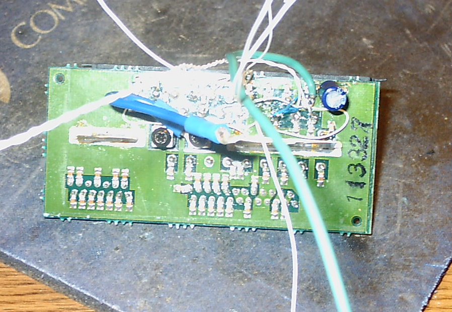
d) Constructing The Control Head and Interfacing With the Rangr
You'll have to build up a control head. A large Radio Shack plastic enclosure works perfectly as it can house the P/C board, the keypad, LCD, the volume control (with an OFF / ON switch), a mike jack and even a small speaker. A 'connectorized' control head may be used with several radios (of the same or different frequency) if the pin assignment convention is the same for each. Since the new M/P uses flash memory, it's easy to change the radio interface.
Note: You may program channels used in any of these radios into their respective 'banks'. There are 5 banks of 20 channels each.
Before applying power, check all connections. A test table shows the resistances and (under power) the voltages at each of the DB-25 connector pins.
Make the resistance tests from the chassis to each of the pins in the DB-25 connector. They should all be close. Correct, as needed. Apply power to the Rangr by grounding the low current power relay DB-25 pin 17 and measure the voltages. When done, remove the ground from pin 17.
f) Construct the Control Head - 'End-to-End' Testing
Build the control head and make the 30 gauge wire connections. Then, connect the control head to the DB-25 cable. Using your meter, verify end-to-end continuity of each lead from the M/P itself to the Rangr chassis. Resolve any discrepancies.
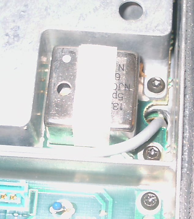
h) Adjusting the Wideband VCO - 2 Meter - High Split Model
The VCO on the Rangr High Split (150 - 174 Mhz) will need to be adjusted to satisfactorily cover the 2 meter ham band.
First, locate TP-201 for the adjustment of the VCO's. It's under the white 'factory adjustment' paper cover on the VCO board in the rear of the radio.
Set the frequency to 148.000 and adjust CV-201 for a reading on 7.0 volts on the meter.
Key the transmitter and adjust CV-202 for as close to 7.0 volts as you can get it. With the one Rangr VHF high split that I've converted, the best that I could do was 5.0 volts, and this was with CV-202 at the bottom of its rotation. Even with this extreme adjustment, the reading at 144.000 Mhz was 3.6 VDC, so there should not be any problems transmitting within the 2 meter ham band as the transmit VCO is well within the recommended 'lock points'.
Using your frequency counter, key the radio and adjust the reference oscillator right on frequency.
No VCO adjustments should be required on the low split model. The software in the M/P will select the proper split within the VCO.
m) 6 Meter Rangr's
For 6 meter Rangr conversions, additional work is required on the VCO's and on the PA stage. Click here for more information.
Crucial Note - Place the fuse right at the car battery. This way, a ground on the power cable running elsewhere in the car will not burn up your car, or cause even more severe consequences! For Rangr's running close to 100 watts, use a 25 to 30 amp fuse. For Rangr's set to 45 to 60 watts, use a 15 to 20 amp unit. Don't omit the fuse as a failure within the Rangr or momentarily reversing the power leads will destroy your investment and hard work.
Turn on the Rangr and select a CTCSS tone. If you have another radio (like a hand held) with CTCSS capability, transmit with the same CTCSS tone selected and verify that the Tone detected LED lights. Next, transmit with the Rangr and set the tone level on the CTCSS board so that it activates your hand held's receiver (set to break the squelch when the correct CTCSS tone is received).
Note: I did not have to adjust the Rangr's internal CG (CTCSS) Deviation Control (RV-604)
Connection Table - Leads Requiring Ferrite Beads Shown in Bold.
|
Function |
Rangr Connection Points & Connector Pins |
Ferrite
Beads |
C-Head Pins (DB-25) |
M/P Board Pins |
Function / Comments |
| On / Off | J-801 Connector - Pin 26 | - | 17 | None |
Low Power Relay |
| Ground | J-801 Connector - Pin 5 | - | see text | MAIN Pin 9 |
Common Ground |
| +13 VDC Power | Switched Relay Connection (see powering considerations) | 2 | 3 | None | M/P Board Power |
| SPI - Enable | IC-704
- Pin 13 (M/P Board) Attach to RX-702 (see text) |
2 | 15 | PLL - Pin 1 | PLL Enable |
| SPI - Clock | IC-704
- Pin 9 (M/P Board) Attach to RX-702 (see text) |
2 | 13 | PLL - Pin 2 | PLL Clock |
| SPI - Data | IC-704
- Pin 5 (M/P Board) Attach to RX-702 (see text) |
2 | 10 | PLL - Pin 3 | PLL Data |
| Transmit | J-801 Connector - Pin 11 | 2 | 1 | PLL - Pin 4 |
RANGR PTT |
| COR (CAS) | J-801 Connector - Pin 12 | - | 5 | MAIN - Pin 1 | 5.1 volt zener |
| Mike High | J-801 Connector - Pin 9 | 2 | 9 | None |
Mike Hot Lead |
| Mike Low | J-801 Connector - Pin 5 | - | see text | None |
Common Ground |
| Speaker | J-801 Connector - Pin 18 | - | 19 | None | No GND! |
| Speaker | J-801 Connector - Pin 20 | - | 20 | None | No GND! |
| Vol / Squ High | J-801 Connector - Pin 7 | - | 25 | None |
Vol / Squelch |
| Vol / Squ Low | J-801 Connector - Pin 6 | - | see text | None |
10K Control |
| Vol - Center | J-801 Connector - Pin 8 | - | 4 | None |
10K Control |
| Sql - Center | J-801 Connector - Pin 15 | - | 8 | None |
Squelch |
| CTCSS OUT |
IC-601 / 4B - Pin 5 (see text) | 2 | 18 | Tones Pin 1 | Transmit CTCSS |
| Chan Change | IC-704
- Pin 33 (M/P Board) Attach to RX-702 (see text) |
2 | 14 | MAIN Pin 6 | PLL Lock & Wideband |
| CTCSS RCV |
J-603 - Pin 1 or J-607 Pin 1(see text) | - | 2 |
Tones Pin 2 | Receive CTCSS |
| TMT OVER | IC-704 - Pin 32 (M/P Board) | 2 | 11 | JP10 - Pin 2 | Transmit Override |
|---|---|---|---|---|---|
| LOCK (PLL) | IC-704 - Pin 1 (M/P Board) | 2 | 6 | JP10 - Pin 1 | PLL LOCK |
| - | No Connection | - | 23 | - | Reserved |
| - | No Connection | - | 24 | - | Reserved |
Test Table - Resistance to Ground and Voltage Tests for 6 Meter and 2 Meter Rangr's. The 10 Meter and 440 Mhz Rangr have not yet been converted or documented.
Note: Ground Pin 17 for Voltage Tests.
Pin # Function 6 Mtr
R/Gnd6 Mtr
Volts440 M
R/Gnd440 M
Volts2 Mtr
R/Gnd2 Mtr
VoltsComments 1 Radio PTT Inf 6.16 Inf 6.18 PTT Lead to Rangr 2 CTCSS IN 9.9K 4.5 .96K 3.3 CTCSS From Radio to the MX-465 Chip 3 M/P Board Power 11K 13 18K 13 13 V Power to External M/P 4 Volume Center Inf - Inf - Volume Control 5 COR (CAS) 11.12K 9 11.25K 9.08 Ensure 5.1 Volt Zener Present on M/P Board 6 Lock PLL Inf 3.62 Inf 3.62 Optional Transmitter Forced Key 7 Ground 0 - 0 - Chassis Ground 8 Squelch Center Inf - Inf - Squelch Control 9 Mike High 2.52K 9 2.6K 9.09 Mike Input to Rangr 10 SPI-Data 10.54K 5 10.55K 5 Serial PLL Data Connection 11 TX Override Inf 2.70 Inf 2.74 Optional Transmitter Forced Key 12 Ground 0 - 0 - Chassis Ground 13 SPI-Clock 11.51K 5 10.59K 5 Serial PLL Clock Connection 14 Channel Change 10.55K 5 10.56K 5 Enables Wideband / Fast PLL Lock 15 SPI-Enable 10.60K 5 10.53K 5 Enable Lead for Radio PLL Chip 16 Ground 0 - 0 - Chassis Ground 17 On / OFF Switch Inf 13 Inf 13 Activates (Fused) Low Current Relay 18 CTCSS IN 11.16K 7.19 1 M 3 CTCSS Lead from MX-465 to Radio 19 Speaker 2.6 K 6.68 Inf 6.64 Don't Ground 20 Speaker 3.3 M 6.68 2.5K 6.66 Don't Ground 21 Ground 0 - 0 - Chassis Ground 22 Ground 0 - 0 - Chassis Ground 23 Reserved - - - - - - - 24 Reserved - - - - - - - 25 Vol / Squelch High 2.2K 4.5 2.19K 4.55 'Hot' Connection for Volume / Squelch Controls G.E.and the product names Phoenix, Delta, Rangr are trademarks of Ericsson General Electric Mobile Communications.
DISCLAIMER - If you follow the steps outlined herein, you do so at your own risk. I cannot, nor will not, be responsible for any possible damage to radio equipment, personal property, to yourself or to others caused by modifications that you may make to the radio as a result of your reading this.
The M/P controls TRANSMITTING and receiving on many frequencies, suitable for a wide range of HF, VHF and UHF needs. In the USA, TRANSMIT operation requires a license issued by the FCC for the class of operation intended. Amateur radio licensees must maintain strict control over their equipment, preventing unlicensed operation within or outside of the amateur bands.
Copyright 2010 - K3JLS