Converting
FT-101 Rigs From Sweep Tubes to 6146B
Type Finals
Important Note:
Before attempting this conversion, know that there are
dangerous and potentially lethal
voltages involved. Unless
you are absolutely
certain that you know what you are doing and have taken the proper
precautions, do
not perform this conversion.
I cannot be
- nor will be - responsible for any injuries or damages
incurred as a result
of your reading this website.
Introduction
Previously
Documented Conversions
Most Recent Conversion - Estimated Costs
- Conversion Overview
-
PA Tube Selection
- Candidate Radios for Conversion
- Starting the Conversion
- Replacing the HV Filter Capacitors
- Reassembling
the Radio
- Neutralization Capacitor
- Higher Power Conversion
- Final Alignment Steps
Hints and Kinks:
- Electrolytic Capacitor Replacements
- Pi-Net
Coil Burned
Connections
- Low Drive / Low Power Output
- VFO
Re-Alignment
- Low Sensitivity / 'S Meter' Indications
- Regulator Board Improvements
- Transmit / Receive Frequency Tracking
1.
Introduction
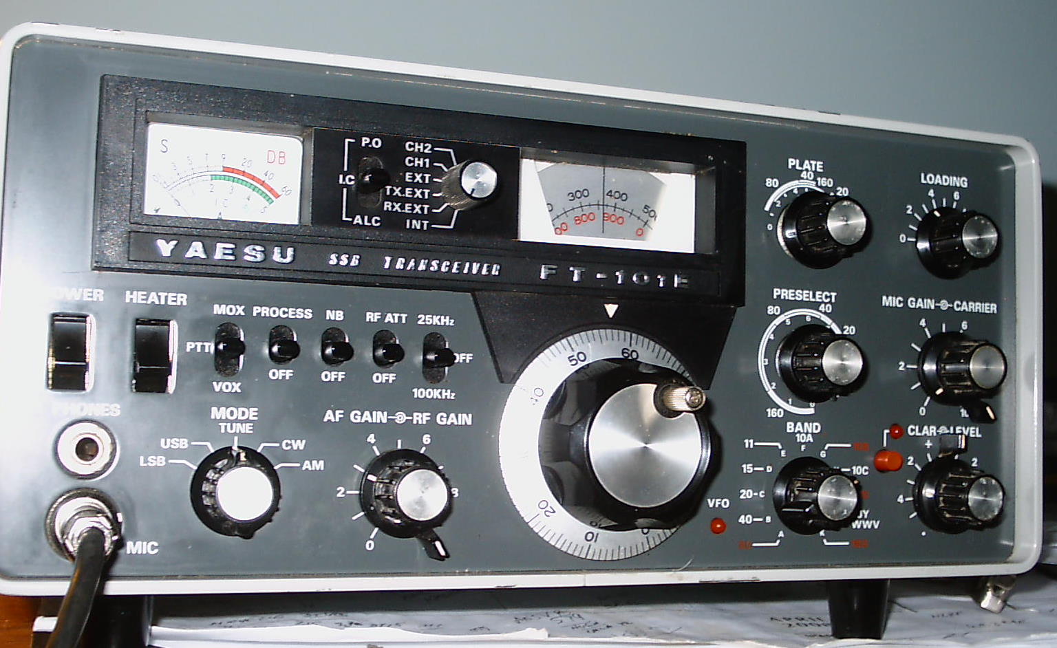
In the 1970's Yeasu produced the
FT-101 series which were well received by the amateur community. Using easy to repair or modify
plug-in boards. and the (then) low cost sweep
tubes found in many TV sets, they were capable of RF outputs of 130 watts on most amateur bands.
Yaesu designed the FT-101 / B / E / EE / EX and F
series around
the 6JS6C tubes. However, their engineers subsequently opted for
the 6146 tubes in their FT-101ZD series. Kenwood did the same in
their hybrid TS-520 / 820 radios. The
deliberate design shift from 'sweeps' to genuine transmitting
tubes was most because sweep tubes quickly became
obsolescent as televisions became increasingly solid state.
There are many
FT-101's that could be pressed back into amateur service if
only the
proper 6JS6C sweep tubes could be found. Regrettably,
perfectly fine
radios are currently being systematically 'cannabalized' and parted out.
2.
First Documented 6146B Conversion
In 1999, Roger Davis -
ZS1J
- wrote a QST article describing how 6146B tubes could be used in an
FT-101B radio. An addendum followed improving the
neutralizing circuit.
This conversion worked for some amateurs,
but others reported
'whistles, pops and cracks' on the higher frequencies
while receiving. These complaints - and
negative comments made on various user groups -
tempered subsequent conversion enthusiasm.
3.
Second Documented Conversion
Bob Goodrich - K7KMQ
- updated the QST
article with one of his own. In it, he shows how he ingeneously solved the
neutralization problem with a 400 pf mica capacitor (instead of the
2000 pf recommended in QST). His website
article
provides some very nice pictorials of his conversion.
4.
Third Documented Conversion - Schematic
- Parts Listing
This follows the work done by the two
'pioneers', offeing an overall description of the
conversion, a parts
listing and a step-by-step conversion process. Interested parties are
invited to improve upon this effort and document their own progress,
either here, or elsewhere. You may email me here.
Note: With new parts, the conversion costs (including the tubes) are about $65 - less for those with a well stocked junk box.
a) How Does
the Conversion Work - a
Low and High Power Option
-
The sweep tubes, their
sockets and bypass capacitors are removed and replaced with new, partially pre-wired ceramic
sockets,
- the fixed neutralizing
capacitor in the PA
compartment is replaced (because
it probably has changed value), a
- new neutralizing
capacitor is added to the
driver stage, and the
- new tubes installed.
- Three other components are also changed in the
screen grid circuit, and a trimmer capacitor added (if 10 meter operation is
desired).
If the user is satisfied with an 'honest' 70 watts output (maybe a bit more) on 160, 80,
40 and 30 / 20 meters (with about 40 / 45 watts on the higher
frequencies), the conversion is finished, except for the
installation of the 10 meter trimmer, setting the bias, neutralization,
etc.
But
if the user wants around 95 watts on the lower
frequencies, additional parts (a 5 watt
wirewound
resistor, three zener diodes, three ceramic capacitors and another
small
diode) needs to be added on one terminal strip.
Two (regulator board) capacitors also need upgrading. Other more
involved steps (described later) can likewise be taken to boost the
output power to close to 115 watts on 160 meters, etc.
b) Which Final Amplifier Tubes
to Use?
Either the 6146B or its 12 volt
equivalent - the 6883B tube - can be used. The 6883B
is a
better choice as it is less expensive and can often be found as NOS
(New Old Stock). The schematic drawing that accompanies this
article depicts wiring for both 6 and 12 volt filament tubes.
You might be able to use 6146A's, but
the output power will be less and the screen grid voltages should be
reduced.. No thought has been given to using the Chinese
equivalents
as their neutralization requirements might be different. Let's buy American if we have a choice!
c) Get A Working, 'Known
Good' Radio, If Possible
The radio chosen for conversion would best be
one whose history is
known, perhaps one's own radio whose finals have weakened or a
radio purchased from a friend. While
suitable radios may be
found on eBay, the buyer is taking a chance that the seller's
description is accurate and truthful.
Before starting, ensure that
there are no open or shorted
power transformer windings. These transformers
are tough to find and
a nuisance to replace. If the radio receives
properly with an antenna connected, and if it will produce some output either at the antenna or
via the transverter jacks, then you may start.
If you have a nice, but non
working radio to convert, if the power
transformer is good, and if all boards are present, you
can repair it using the FT-101
Service Manual. Depending upon the
nature of the problem(s) and
the time you have available, you may need a signal
generator and a 'scope.
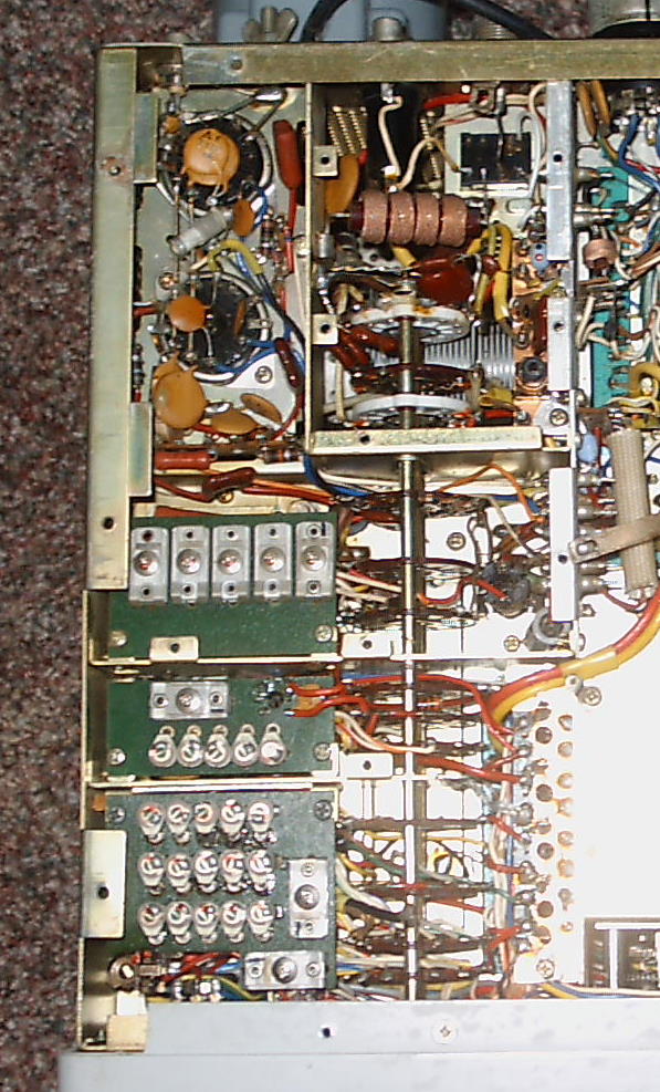
d) Starting the Conversion - Here's the Schematic
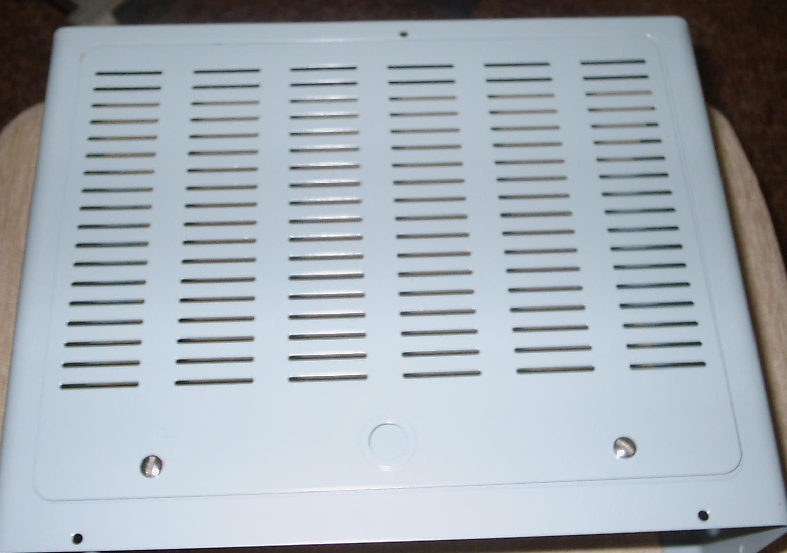
Get a container for the
screws and, with ith the radio unplugged, remove the top and
bottom
panels from the radio, followed by the wrap
around cover.
Note: This
is a good time to
repaint
the case, sanding it down and applying two coats of automotive primer. Give the primer a day or two to dry,
wet sanding as needed. The finish coat paint is
Rustoleum Painter's Touch, Ultra
Cover - Gloss - Winter Gray,
an excellent match -
Home
Depot.
Let
the finished
coated pieces bake in the sun for a couple of days to give the finish
coat ample time to harden.
- Using
an insulated screwdriver, short circuit one of the sweep tubes plate
caps to ground. While the radio has been unplugged and while
the
bleeder resistors should have long drained any residual charge in the
capacitors, it always pays to be safe to avoid a nasty shock.
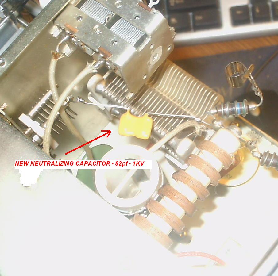
- Identify
C125, either a rectangular 1KV mica capacitor in the
PA
compartment. Replace C125
with an 82 pf
1KV mica unit. This
is a
preventative step as C125 has most probably changed in value due to its
proximity to the sweep tubes or may have been changed from 100 pf
to a 10 pf
unit to accommodate American made 6JS6C tubes, per Yaesu's
recommendation.
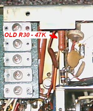
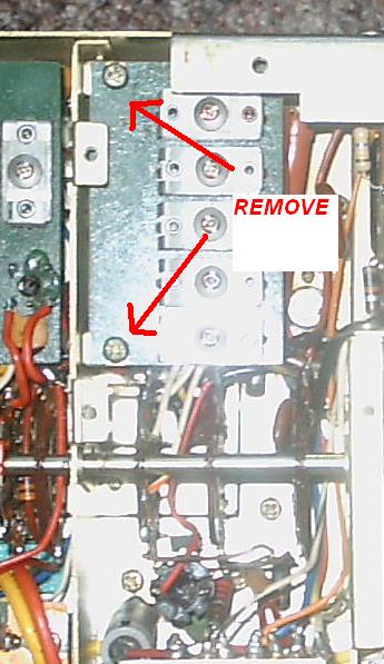
- Remove the PA cage bottom. Identify, remove and discard R30,
a 47K 1 watt
resistor on a terminal strip adjacent to the PA compartment.
- Replace R30 with a 470K,
1/2 watt resistor. This
prevents PA tube flash over when the screen grid voltage is removed and
is VITAL
.
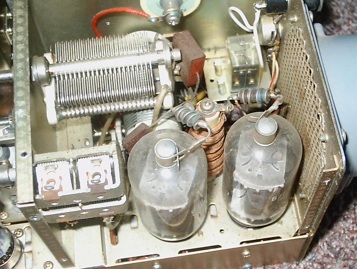
- Locate the two 12 pin PA sockets, and unsolder
R14 (100 ohm), R9, and the black coaxial cable inner conductor. Unsolder all ground connections, decoupling
capacitors and blue heater wires. When done, a blue wire
will be totally disconnected - save it!. Don't
unsolder the ground end of R12.
- Unscrew
and save the 4 Phillips screws and remove and discard the tube
sockets
and decoupling capacitors. Clip some of the
longer
wires from the sockets as they will be used later.
- Remove and discard J5 (transverter feed) and C16
(coupling capacitor) as they may interfere with the installation of the new bypass capacitors.
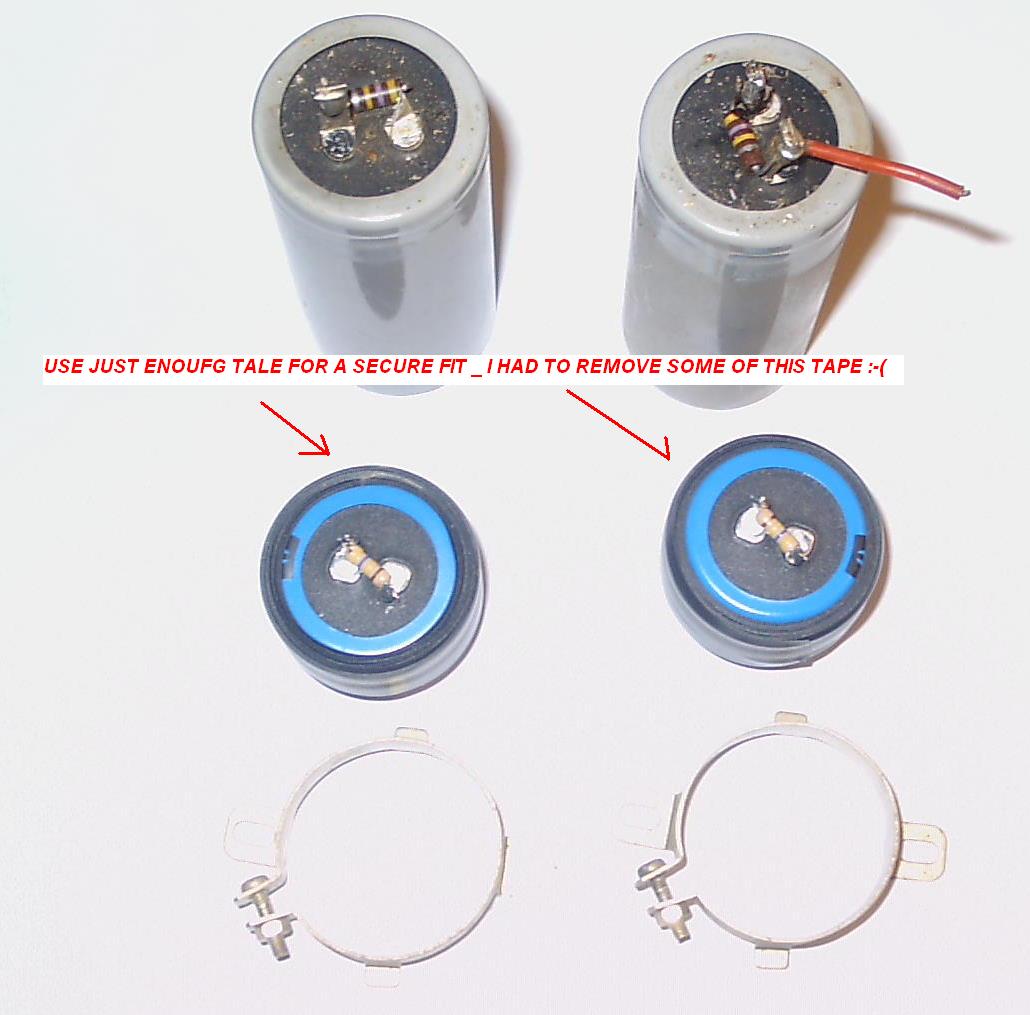
e) Replacing the HV Filter
Capacitors with Low Profile Units
This is a good time to replace C77 & C78 as failure here
could damage the power
transformer. If you are NOT replacing them, continue here.
- To replace
C77 and C78,
unpower the radio and remove the regulator and noise blanker boards.
- Remove the 4 screws holding the clamps on the large
electrolytics and turn the radio over.
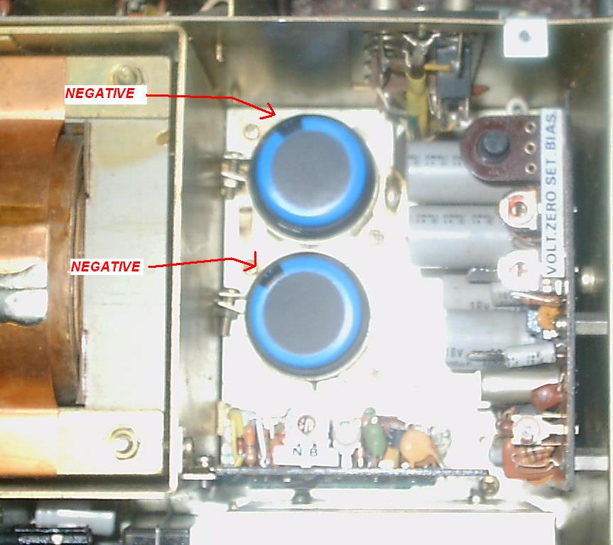
- Note the capacitor wiring and polarity. The replacements must be
installed in exactly
the same
way or they will explode.
- Using
cable ties, pull the wiring that is not associated with the capacitors
up and out of the way so that it will not be burned when soldering.
- Using
heavy gauge wire clippers, sever the capacitor lugs and the
capacitors will fall out of the radio. This ensures
that the proper wires will be put on the right lugs on the new
capacitors.
- Remove the clamps and discared the capacitors.
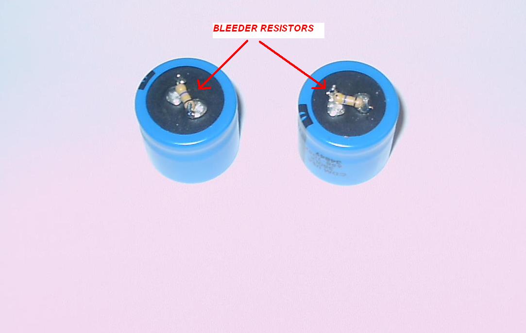
- Install new bleeder resistors (1/2 watt
470K). Reusing old carbon bleeders is like reusing toilet
paper.
- Install and tighten the 4 screws.
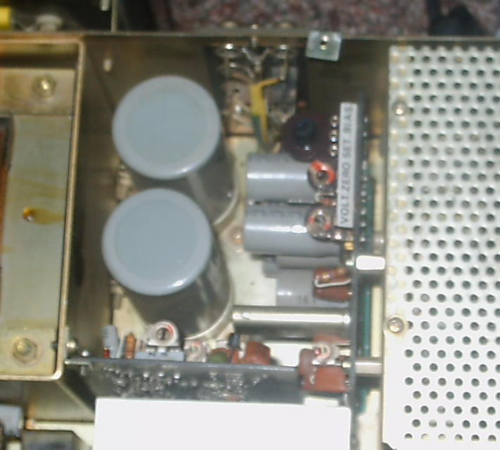
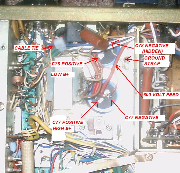
- Turn the radio over and examine the underside where the
capacitor wiring will be placed.
- Here's a picture.
Make the GROUND connection to the NEGATIVE side of C78.
You'll need to add a longer wire to the chassis
spot
where the original wire was grounded. Use a high temperature
soldering iron or soldering gun.
- Solder the
wires originally removed from the POSITIVE side of C78 to the POSITIVE
side of the new capacitor. One of these wires
will be connected to the NEGATIVE side of C77. Crimp these
wires
before soldering. (You
may remove the red wire connected to pin 4 of J14 if you find it
difficult making all the connections).
- Connect and solder the short red wire from the POSITIVE
side of C78 to the NEGATIVE terminal of C77.
- Connect the remaining 2 red wires and the heavier insulated
wire to the POSITIVE terminal of C77.
- Double check your work and then reinstall the transformer.
- Reinstall the regulator and noise blanker boards.
f) Reassembling the Radio
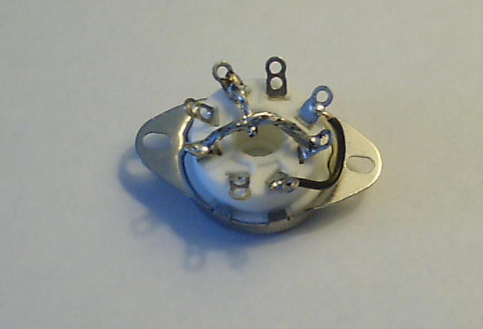
- 'Prep' the new ceramic octal tube
sockets. Pay
particular attention to the areas for the
ground connections for the filaments and bypass capacitors.
When
soldering to the chassis, use points to which the original
wires
were attached. If necessary to solder elsewhere, thoroughly
sand the coating off the
chassis so that the steel beneath it shows clearly. If not done, the solder
will not adhere. Tin the spot
before
making the connection with a large iron or soldering gun.
Lots of heat is required.
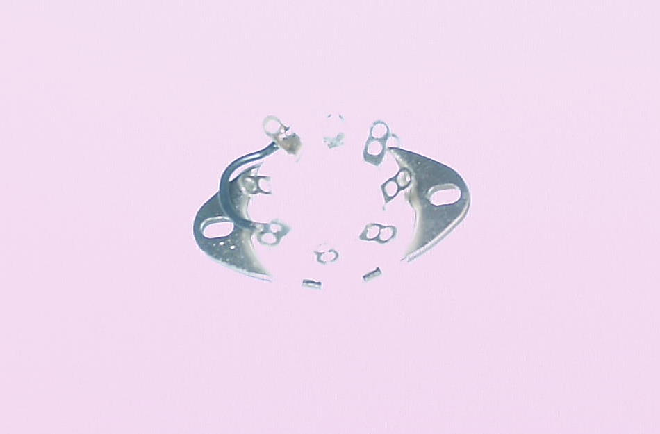
- For
the 6883B's, the 12 volt filaments
are wired in parallel.
Using a short length of hookup wire, connect pin 8 on each socket to
pin 2. Make these connections on the bottom hole
of each lug, as shown.
As pin 2 of each socket will be connected to the chassis
later, this also grounds pin 8 (the tube's shield ring) and eliminates
the need for another chassis connection. Then go
here.
- For
the 6146's, the 6 volt filaments are
wired in series
(as they were for the 6JS6C's). Therefore, only one pin 2
will be grounded while pin 2 of the other tube will be connected to pin
7 of its mate. Connect pin 2 to pin 8 (bottom holes) of the
6146 tube closest to the rear of the chassis.
- Fit the 2 new sockets with the keyway facing the chassis
center and secure with the saved screws.
- Using
a
scrap of previously saved wire, jumper the top hole on pin 1 of
the tube closest to the rear of the chassis to the top hole of pin 4 on
the other tube - effectively bridging the cathodes (pins 1, 4 and 6)
together.
- Reconnect
both the hot end of R12 to this jumper and the (previously
unsoldered) inner conductor of the black coaxial cable.
Connect the ground of the coaxial cable to a suitable nearby
ground (say, to pin 8 of the nearest tube) This is
the lead used to measure the final tube plate current.
- Place
a .01mf 1.5 KV bypass capacitor (C3* and C6*) from either pin 1, 4 or 6 -
wherever convenient - (top hole) at each output tube to ground.
- Connect (but don't solder) the blue wire (12 volt
AC filament connection) from the chassis to pin
7 (bottom hole) of the output tube closest to the center of the
chassis.
- For
the 12 volt 6883B tube, ground pin 2 of each
tube. Using the spare blue wire from the old sweep tube arrangement,
'jumper'
pins 7 of both tubes together (top hole), but do not solder yet. Then
continue here.
- For
the 6 volt 6146 tube, ground pin 2 of the
tube closest to the rear of the chassis. Using the spare blue
wire from the old sweep tube arrangement, 'jumper'
pin 7 of the rear tube to pin 2 (top hole) of the tube closest to the
center of the chassis.
- Place
a .01mf 1.5 KV bypass capacitor from each pin 7 (top hole) to
ground
(C2*and C4*), bypassing the filaments.
Solder all connections.
- Connect pins 5 (top hole) of each output tube together with
insulated wire.
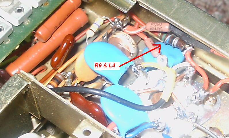
- Connect R9 (L4
wrapped around it) to pin 5 of the closest tube, providing both bias
and RF input.
- Remove and discard R14, a 100 ohm 1/2 watt resistor
connected to the hot side of the new R30, now 470K.
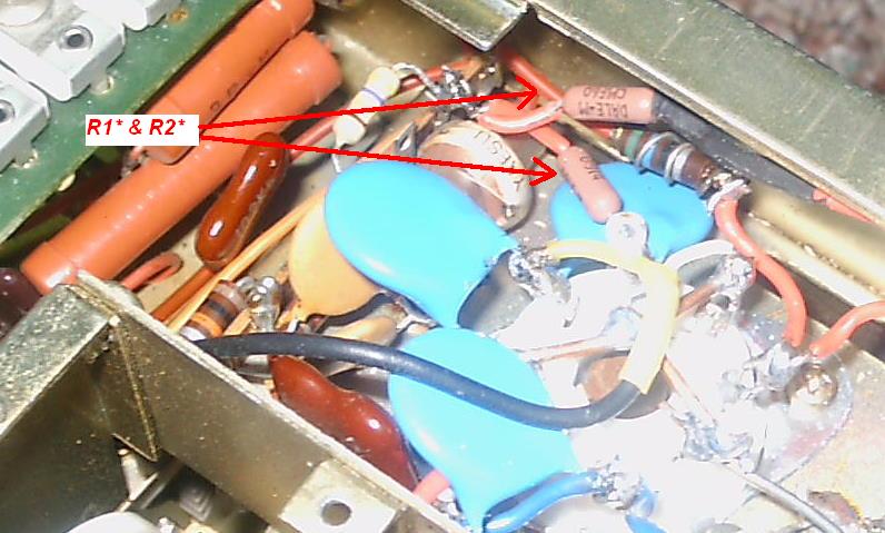
- From
the 'hot' side of R30, connect R1*
and R2* to pin 3 of each 6883B tube. These resistors
are 1% 100
ohm, 1/2 watt units and will limit the current applied to each 6883B
screen grid to
the same, safe level.
- Connect C1* and C5* from pin 3 of each 6883B tube to
ground. These are .01mf 1.5 KV ceramic bypass capacitors.
- When
done, verify your work, especially the connections made to ground, the
'new' R30, and R1* and R2*.
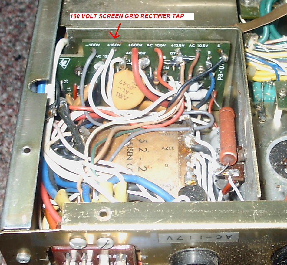
- Remove the wire that connects to the 160
volt tap on the rectifier board.
- Temporarily remove the regulator board as filter
capacitors C7 and C8 will interfere with the following measurement..
- On each of the output tubes, measure the resistance of pin
3 to ground. Make sure it reads in the vicinity of 470K ohms.
Note: For
the High Power
conversion, Regulator Board
C7 and C8 (22
mf) should be changed
to 350 volt
units to provide an adequate safety margin for the increased screen
grid
voltage. These capacitors 'stiffen' the voltage and
minimize voltage swings and IMD problems.
- If
you are performing the Low Power
conversion, reconnect the wire
to the 160 volt tap on the rectifier board. For the
High
Power conversion, this lead will be connected later.
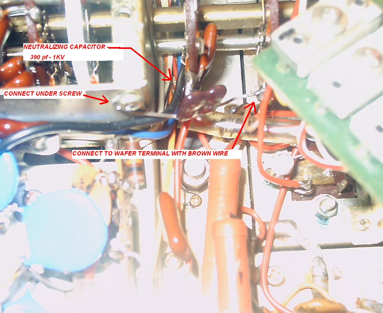
g) Neutralization
Capacitor
A new 390 pf 1KV mica capacitor is installed on
the driver's output side for neutralization. Failure
to do so may cause premature PA tube failure.
- Remove the two screws holding the trimmer
board (containing
trimmers TC-6 to TC-10) and carefully move it aside.
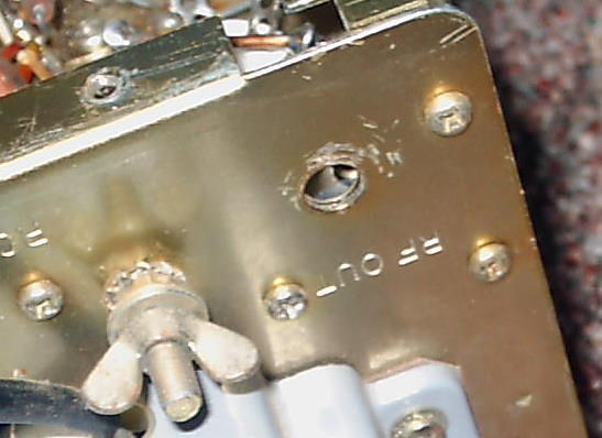
- Connect
a 390 pf mica capacitor from under one of the sheet metal screws over
to the switch wafer pin with the brown wire on it, as shown.
Position the
capacitor vertically
so that it will not interfere with the neutralization
adjustment to be done later.
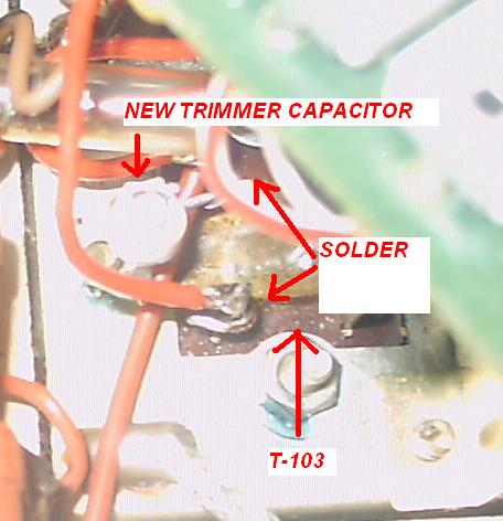
h)
Padding Capacitor - If you don't plan to
work on 10 meters, skip this step.
Due to the reduced interelectrode capacitance of the new tubes, a small
trimmer capacitor must be added across T103.
- Solder a 5 - 40 pf trimmer capacitor across the two T103
coil
terminals.
First solder short lengths of stiff wire to one terminal, bending it into a 'V'. Crimp and solder
one
lead. watching for crosses underneath. Then, bend the other wire into position and solder it.
If satisfied with the 70 watt
Low Power option, do the final alignment.
For close to 100 watt output on the lower
frequencies,
then continue below:
i) Higher Power Conversion
The FT-101 power transformer supports the
6JS6C tube. While not built for RF service, this tube can
generate more RF that the 6146 and at lesser voltages.
However, 'sweeps' can
be easily be damaged by improper tuning, over driving and higher than
designed AM output levels.
When wired with the 117 volt taps, the power transformer will supply about 625 volts to the
plates and 165 volts
to the screen grids in the 'no load' state. The screen grid tap on the power
transformer
also supplies final amplifier bias.
If the screen grid voltage were higher, the FT-101 would be able to produce 80 to 90 watts on 80 meters. But
unfortunately, it doesn't.
About 220 volts is needed on the screen grids
of the finals to help them develop maximum output power with the existing power transformer.
The goals are to maintain relative voltage stability (to minimize IMD)
without exposing the screen grids to more than
250 volts (as specified in the datasheet).
So, a 5
watt 5.6K resistor connects to a zener diode series
arrangement limiting the screen grid voltage to around 230 volts. This circuit also
contains
an isolation
diode (protects the
power transformer from a plate to grid short - a valuable suggestion
by N4ML).
All this fits on a 7 lug terminal strip.
Note: Once
'warmed up', this dropping resistor / zener diode arrangement draws
about 18 ma. while receiving and 11 ma. when transmitting. There doesn't appear to be any over heating
problem especially since the 6883 / 6146B's draw less filament current
than the 6JS6C's.
Admittedly,
the resistor zener diode combination will generate some
under-the-chassis heat even when the filaments are turned off.
This has not proven to be a problem in the radios that I've
converted. However, if the user would like to eliminate this
heat, a supplemental relay may be installed below the chassis as described on this link.
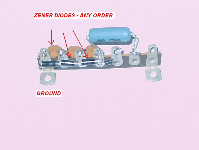
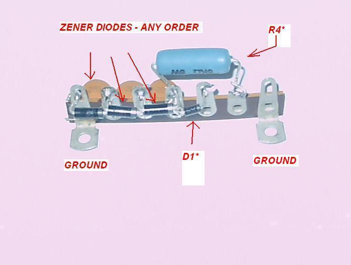
To prepare the terminal strip
before installing it, first:
- mount the zener diodes (D2*, D3*, D4*), add the
- zener diode noise suppression
capacitors C9* ,C10*, C11*; add the
- 1N4007 screen grid isolation diode D1*
, and add
- R4*, the 5 watt, 5.6K wire wound resistor.
The terminal strip may be soldered directly to the chassis.
Before soldering, thoroughly sand the areas where the two 'feet' will be mounted. Use a pair of 'vice grips' to hold one of the lugs flat while you solder the other.
Once done, connect the two wires (one from the NEGATIVE side of C77,
and the wire removed from the 160 volt rectifier tap), double check
your work and turn just the power switch
on.
Then,
verify
that there is approxinately 230 volts on the PA tube screen
grids.. Turn on the filament switch, wait for 60
seconds (for the tubes and zeners to warm up), and adjust the bias (below).
Note: Take care that your components will not short out to the bottom plate when it is installed.
Also Note:
I have some terminal strips if anyone
needs them - for just the cost of the postage.
j) Final Alignment Steps
- Setting the Bias,
Neutralizating the Finals and Adjusting the 10 Meter Trimmer Capacitor
i) Setting
the Bias
With both power switches in the ON
position, place the function switch in either the LSB or USB position,
operate the MOX switch and adjust the PA bias to 60 ma.
Release the MOX switch, turn both power switches off and
unplug
the radio.
Important Note:
if you are using the supplemental relay, wait about 15 seconds before
setting the bias. This allows enough time for the zeners to heat
up so that the voltage will be at its maximum.
ii)
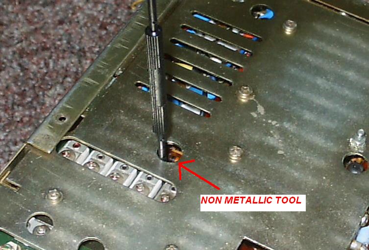
'Cold' Neutralization - Thanks to Peter Roberts - G4DJB - Please Review Before Attempting
Neutralization minimizes signal feed
thru by coupling a signal back to the driver
equal in amplitude but opposite in phase. Use a non metallic adjusting tool
as there are lethal
voltages present:
- Screw down
the top and bottom covers of the PA compartment (important).
- Remove the
"Accessory" plug from the rear panel, opening the heaters in the
final amplifier tubes.
- Connect
the antenna connector to a dummy load of at least a 1 watt 50 ohm
resistor.
- Connect
either a high impedance VTVM or scope probe to the 'hot' side of the
dummy load.
- Switch on
both power switches. (The
PA tubes will not be lit, but the 12BY7A's filament will be).
- Set
frequency to
29.0 MHz and set the mode switch to TUNE.
- Set the
carrier
level control to about 3 and set the MOX/PTT/VOX switch to MOX.
- Adjust the
Preselector, Plate and Load controls for MAXIMUM signal on the
VTVM/scope. Adjust the carrier level as needed.
- Adjust the
neutralization capacitor TC27 (using
a
non-metallic
tuning tool)
for
MINIMUM signal on the detector.
- Re-peak
the Plate
and Load controls for MAXIMUM and re-adjust TC27 for MINIMUM.
- Repeat
until no further signal reduction is possible..
- Release the
MOX and turn the radio totally off.
- Remove the
detector from the ANT connector and replace
the Accessory plug.
- Maximum RF
output should now coincide with the plate current dip (or be very close
to it).
iii)
Adjusting the 10 Meter Trimmer Capacitor
- Set the radio to 28.000 Mhz with the preselector set to the
beginning edge of the 10 meter band.
- Turn the radio off, unplug it and turn it over.
Remove the bottom cover of the PA compartment.
- Remove
the two screws securing the trimmer board, and raise it above the
chassis for access to the newly installed trimmer capacitor.
- Insulate the board from the chassis as there are high
voltages present on it - be careful!
- Turn the radio (both switches) on and connect a dummy load.
- Operate MOX and adjust the PA Tune and Load
controls for maximum output on 28.000 Mhz.
- Using an insulated alignment tool, adjust the trimmer
capacitor for maximum output.
- Release the MOX switch and turn the power off.
- Reinstall the PA compartment bottom cover.
- Turn the radio back on (both switches) and complete the 10
meter alignment as described in the service manual
Before replacing the radio in its case
you may want to perform a complete alignment
per the service manual as some additional capacity has been added to the T103 circuit..
When finished and if you've selected the High Power
option, and if your line voltage is around 117 volts, your radio should put out close to 95 watts
on 160, 80, 40 and 30 meters, close to 90 watts on 20 meters, and less on the higher frequencies (which is to be expected).
Note: If the line voltage is less, then the RF power will be somewhat less.
k) Capacitor Replacements
You
may want to replace all the electrolytic capacitors as they
can become problematic as they dry out. There is an
eBay vendor who offers a complete capacitor kit with instructions,
claiming that the complete conversion can be done in 4 to 6 hours.
I ordered the
parts from Mouser and it took me a lot longer, but
it was a relaxing
activity in its own peculiar
way.
While apart, consider replacing C131 and C13 with 1KV
mica units. These capacitors have been known to fail with
sometimes catastrophic results.
l) Pi-Net
Coil Burned
Connections
Inspect the connections underneath the
pi net coil for burning. If the previous
owner was a 'Golden
Screwdriver' who
flogged it on 11 meters, then there's a good chance that the
10
meter coil tap and the one that feeds C25 may both be burned.
This happened on one of the radios that I converted.
For
more information, check out the following W4CLM post which describes
the problem / solution in detail: http://groups.yahoo.com/group/FT-101/message/3164 . Carol
does really nice work, doesn't she?
m) Low Drive / Low Power Output
If you are unable to get at least 90 watts out on 80 meters with a new
set of final amplifier tubes, you may want to check the high voltage.
Rather than opening up the PA compartment (can be dangerous),
measure the voltage on the 600 volt 'tap' of the rectifier board
beneath the chassis. Under no load, it should be in the vicinity
of 625 volts, and under load - around 590 volts. If the voltage
is significantly less, then one or more of the rectifier diodes may be
'marginal' or leaky, especially if the radio was owned by the bane of
the FT-101, the worldwide illegal CB operator.
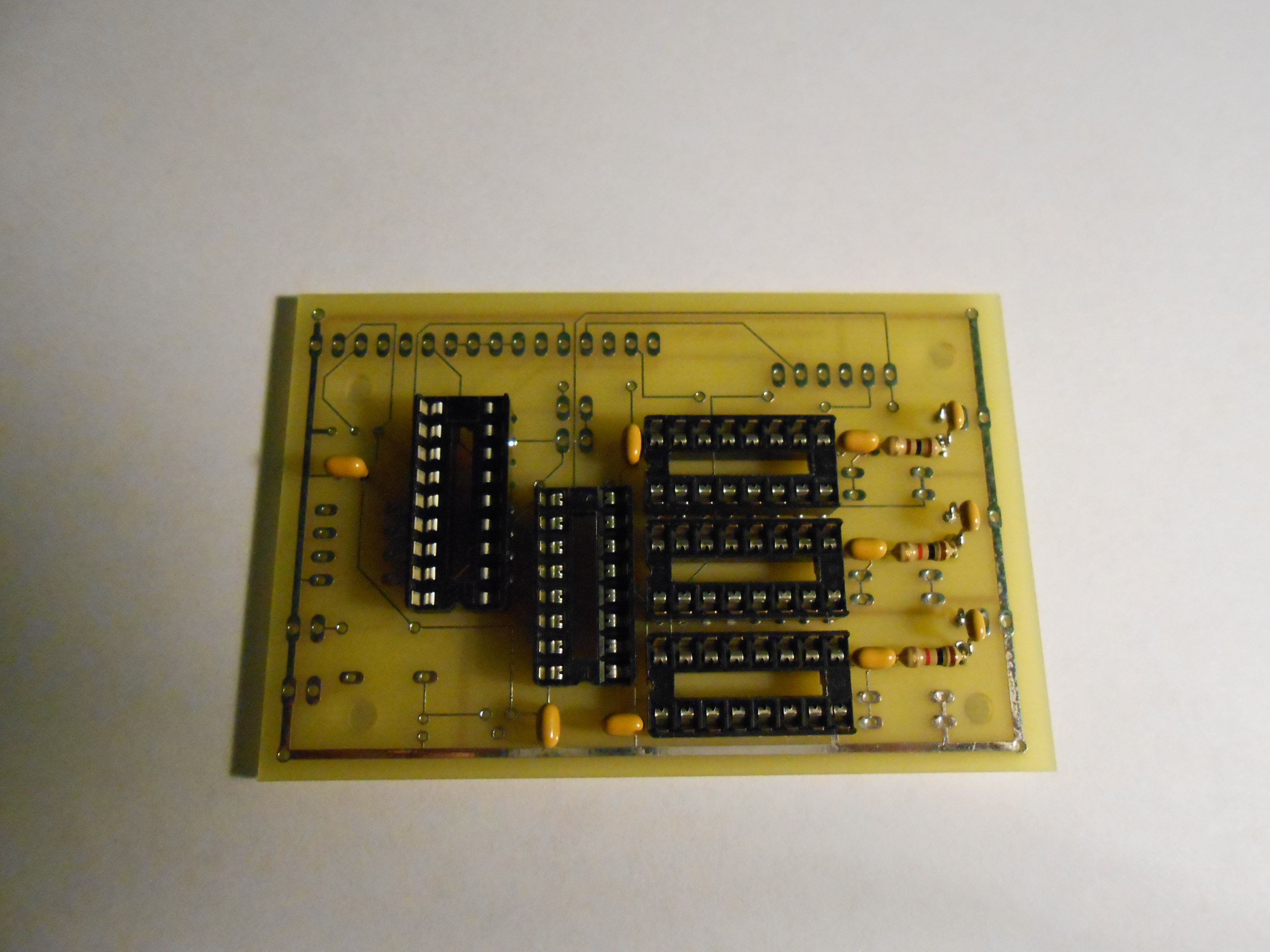
It can be difficult to find a maringal diode under load. The best way
to solve this problem (if you think you have it) is to replace all 8
diodes with 1N4007's. The P/C board solder mask shows correct
diode orientation. While you're at it, replace the 8 470K
resistors and any other component that may be burned and / or out of
tolerance. In one of my converted radios, R1 - a 5.6 ohm, 2 watt
resistor - was severly burned, was still operational, but was also
replaced.
C11, a 1KV 200 pf unit on driver plate often
becomes 'leaky', reducing drive. It's impossible to
remove
C11 as it is buried underneath the bandswitch.
However, by clipping the lead of C11 that connects to the
bandswitch at the same point (brown wire)
where the new neutralization capacitor is attached,
C11 can effectively be replaced with a new unit.
If
you are experiencing a low drive problem when in the TUNE, CW or AM
modes, take a look at the setting of TC5 on the modulator board. This
capacitor is used to peak the output of Q2, the AM Modulator / CW
buffer. The CW signal is used when tuning up.
Place your scope (or
VTVM) probe on the 'hot' side of the Drive control and then adjust TC5
for max
signal while
in the MOX mode.
TC5 can be reached from the top of the chassis if you use a long non
metallic adjustment tool. You can also check the setting of the CW
trimmer while you are there.
n) VFO
Re-Alignment
If the top scale of your VFO is out of
alignment, it may be realigned
by adjusting a trimmer on the top of the VFO (the speech processor vill
have to be temporarily removed if your radio is equipped with one).
Facing the radio, adjust only the trimmer on your LEFT.
The
trimmer on the RIGHT should NOT be touched as it was calibrated at the
Yaesu factory to minimize VFO drift.
o) Low Sensitivity and No 'S Meter' Indications on Weak Signals
If
you experience poor sensitivity on all bands, if your S Meter refuses
to budge on all but the strongest of signals, and if the marker
generator will cause the S meter to properly deflect, check out the
little lamp / fuse on the rear panel. This is a protective device
designed to save the RF amplifier circuit from damage if the radio is
exposed to a strong RF signal (say, at Field Day). If the lamp is
open, the residual capacity within the bulb will be adequate for the
radio to detect weak signals, but the S meter won't move. For
what it's worth, there was a GE #47 bulb in my radio.
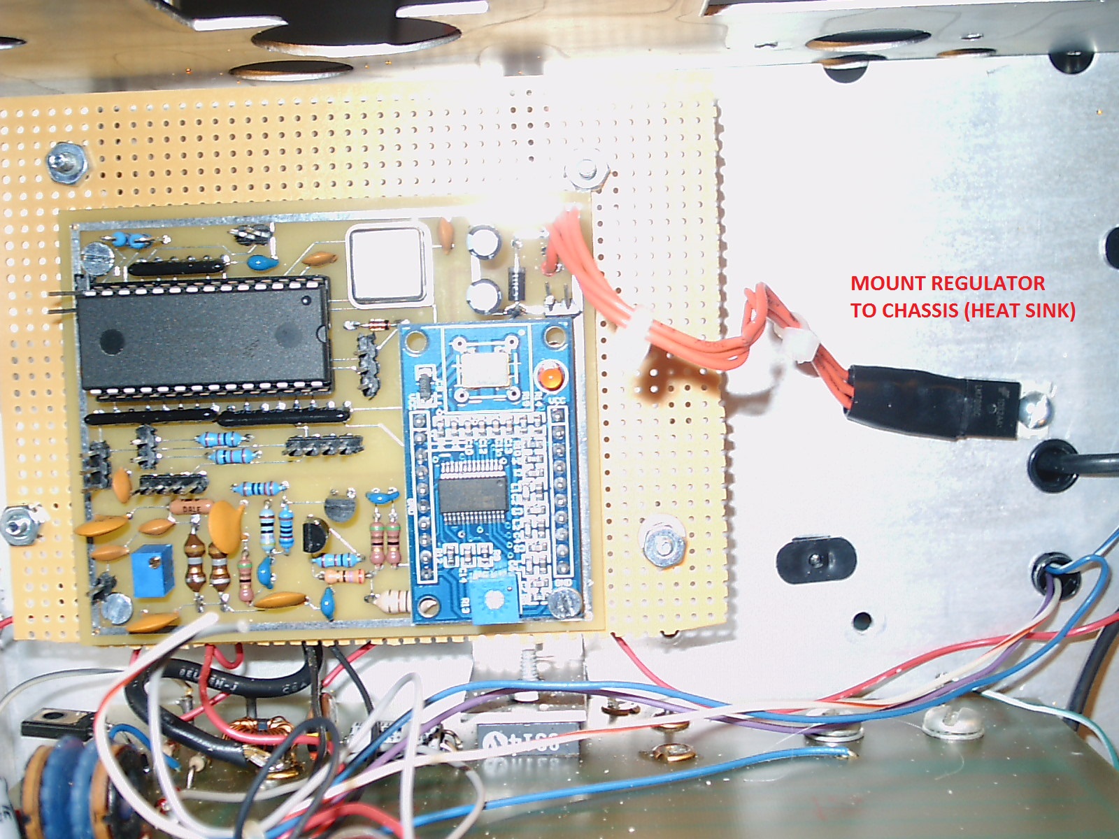
p) Regulator Board Improvements - PB-1314
Remove the bottom cover, let the radio warm up for a
bit and measure
the voltage on the '6 volt reg' input to the VFO. Set it to 6 volts
(VOLT adjustment) and watch it for an hour or so. If the voltage starts
to drift with heat, the frequency of the radio will also drift - bad
news! The obsolete voltage regulator chip on the regulator board is
intermittent - quite common with the older PB-1314 Regulator board.
To fix it, remove the regulator chip, the associated components and the
solder traces. Install an LM-7806 chip with a .33 mf on the input side
and a .1 mf cap on the output. This solution was suggested by N9WB and it works
great - no more voltage drift! You can also remove the VOLT trimmer as
it will no longer be needed. Why confuse the radio's next owner?
q) Transmit and Receive Tracking Adjustments
There are at least 3 ways to accomplish this:
1) If you have
another SSB transceiver, connect a dummy load to it, send an SSB signal
and tune your FT-101 until the voice sounds 'natural'. Place the dummy
load on the FT-101, operate PTT and talk into the mike, listening with
the other radio. Adjust the ZERO trimmer on the regulator board until
your voice sounds natural.
Note:
If the ZERO trimmer runs to one extreme or the other WITHOUT producing
a 'right on' signal, then perform the CLARIFIER ADJUSTMENT as described
in the service manual, and repeat..
2) All you need is an inexpensive HF SSB receiver. Pick a band
and place your receiver next to the FT-101, and set it to either
LSB / USB. Tune your monitor receiver between 8700 and 9200 kHz and
listen for the VFO beat tone. Set the receiver fine tuning to give you
a tone you find pleasing to your ear. Press the PTT switch and listen
to the tone. You will most likely hear a shift. Set the "zero" pot on
the regulator board to eliminate the tone difference. You can do this
adjustment to get the difference down to about 5 Hz; or whatever your
ear can detect. It's simple, and it works. - from W4CLM / K6WWH.
3) Connect an accurate digital voltmeter to the CLARI input to the VFO.
Place the radio in the LSB /USB receive mode and note the voltage.
Depress PTT, wait a second or two and then while holding PTT, adjust
the ZERO trimmer until the voltage EXACTLY matches the receive mode
voltage. Repeat several times to ensure that you hit the 'sweet spot'.
If this doesn't work properly, you may have to perform the CLARIFIER
ADJUSTMENT and then repeat
DISCLAIMER
- - If you follow
the steps outlined herein, you do so at your own
risk. I cannot, nor will not, be responsible for
any possible damage to radio equipment, personal property, to yourself
or to others caused by modifications that you may make as a
result of your reading this.