Six Digit
LED Frequency
Display for the:
Heathkit
SB, HW, HR Series
Kenwood
TS-520(S / SE)
Heathkit SB-104 / 104A
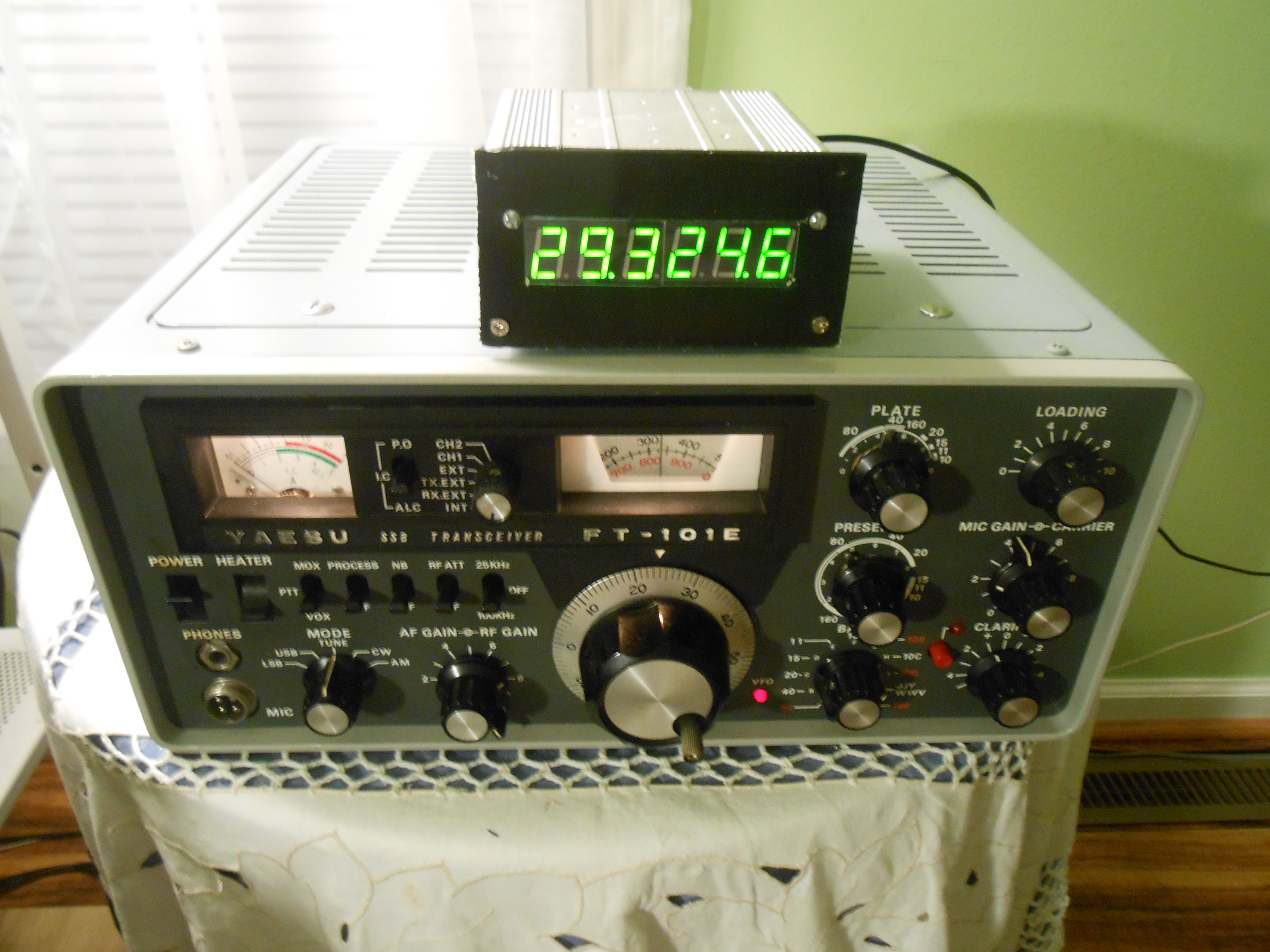
Yaesu
FT-101 Series - Available
Soon
- Radio Connections (see below)
1. Introduction
The PCB (and the software) have been
redesigned to allow
a 6 digit LED display (TM-1637 chip -
controlled serially
by the PIC processor) to be
used. Jumpers (options) on the new board allow the design
to serve the Heathkit family of radios, the Kenwood TS-520S / SE, the
Yaesu FT-101
and (later) the Collins radios. It can also be used as a
simple frequency
counter. Thus
far, the code has been written
for
the Heathkit and Kenwood TS-520 radios and for the Yaesu FT-101
family.
Note: Bare-bones boards with pre-programmed PIC
processors
are available for
others who might like to build one.
Also Note: The main
thing to remember about this display is it's inherent and consistent accuracy.
As it constantly
measures the frequencies of the HFO, BFO (Carrier
Oscillator) and VFO the display is always smack on even were one of the
oscillators were to drift slightly. This is a step above some
of the
other frequency displays (like the Yaesu 601B) that measure just the
VFO frequency and then compute a result based upon previously
customer-entered frequencies. There are no switches for band
or for mode
selection.
It just
transparently works.
This
website will first show how how to build and test the board and it
includes references to the Mouser parts used. Later sections
show
how to interface it with the desired radio.
If you are interested, then please read on.
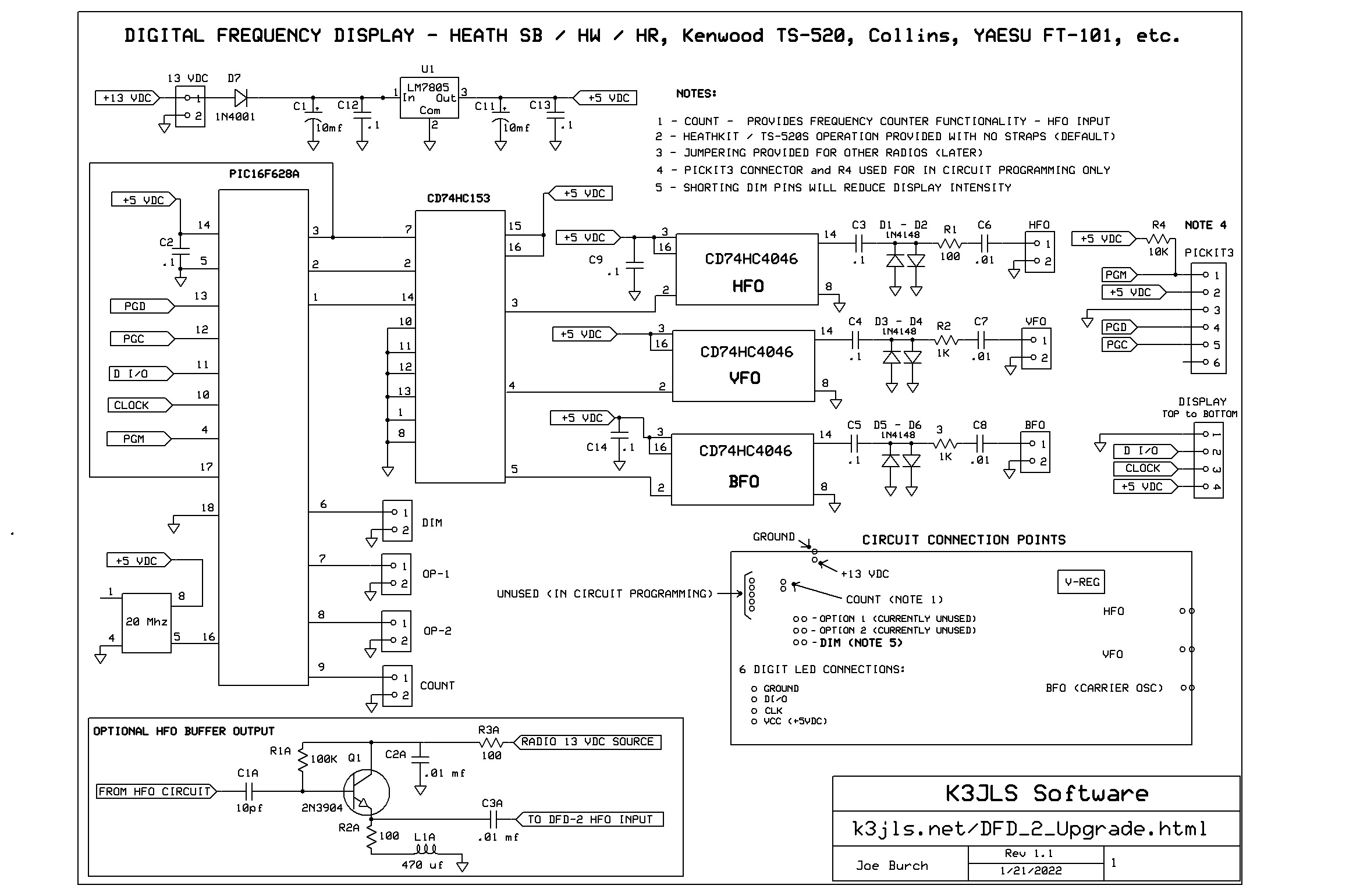
2.
Design
and Schematic -
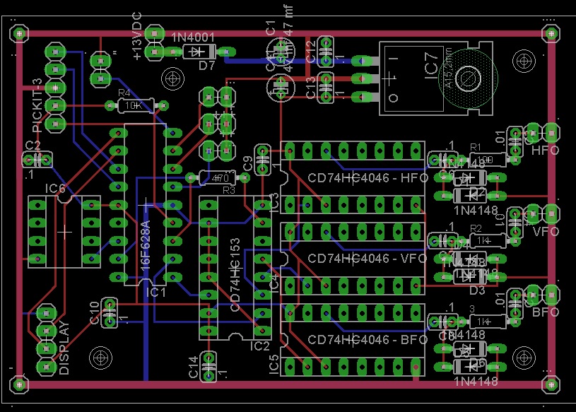
Phase 4 Board (Current)
P/C
board design:
- the very compact PCB (just 5 integrated circuits is just 2"
by 3" - ideal
for installing within the radio itseld for a neat and tidy job,
- chassis
mounting holes have been provided should the user desire to mount the
unit against the chassis (with the appropriate standoffs),
- no 'hang on' auxiliary processors, reset buttons, LEDs, or
anything extraneous,
- no alignment required -
assemble it properly and it just....WORKS!
- PCB mounted components cost just $16 (Mouser - referenced
below) or less if one has comparable junk box parts
- 6 digit displays are found on eBay, Amazo and Walmart for
less than $10.
- you'll need some miniature coax, connectors, parts for the
display enclosure, and ample coffee.
3. Construction
Details (read on down)
1) Refer to the
printed circuit board layout
and
to the
schematic
as you procede.
Mount
components on the silkscreened
side of
the board:
Important Suggestion
- when soldering the pin headers (next step), you might first want
to first place them in a spare integrated circuit socket or in a female
header pin set (usually available on eBay). This
way, the heat
of your soldering iron will not melt the plastic and cause the pins to
seat unevenly. I've soldered hundreds of pins this way and it
always
works.
2) Mount the Pin Headers on the board .
Note: no
need to install PICKIT3 header or resistor R4 as they are used by me
only for in circuit programming:
- Mouser
932-MIKROE-1316
- (1
required - $.72)
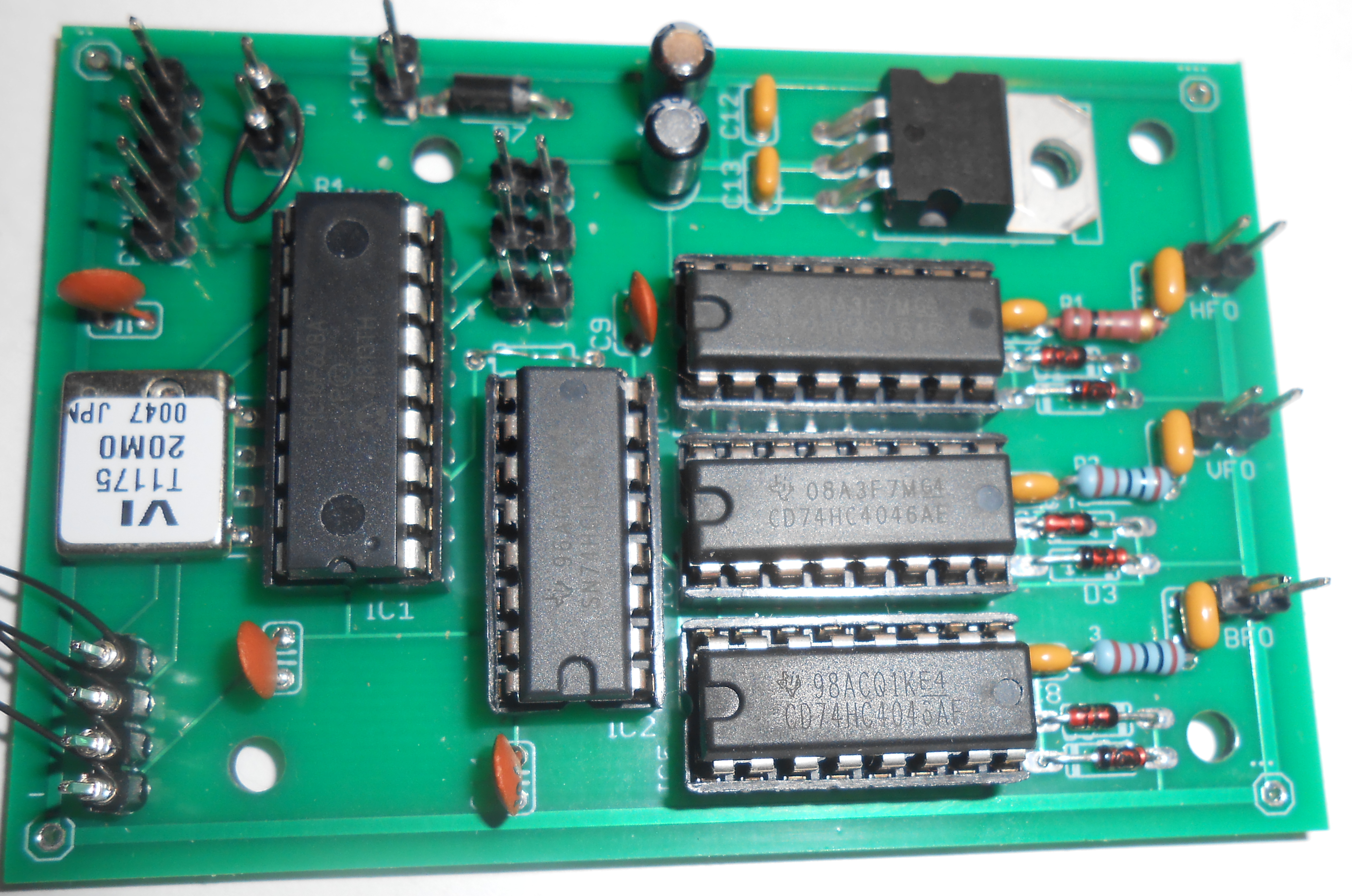
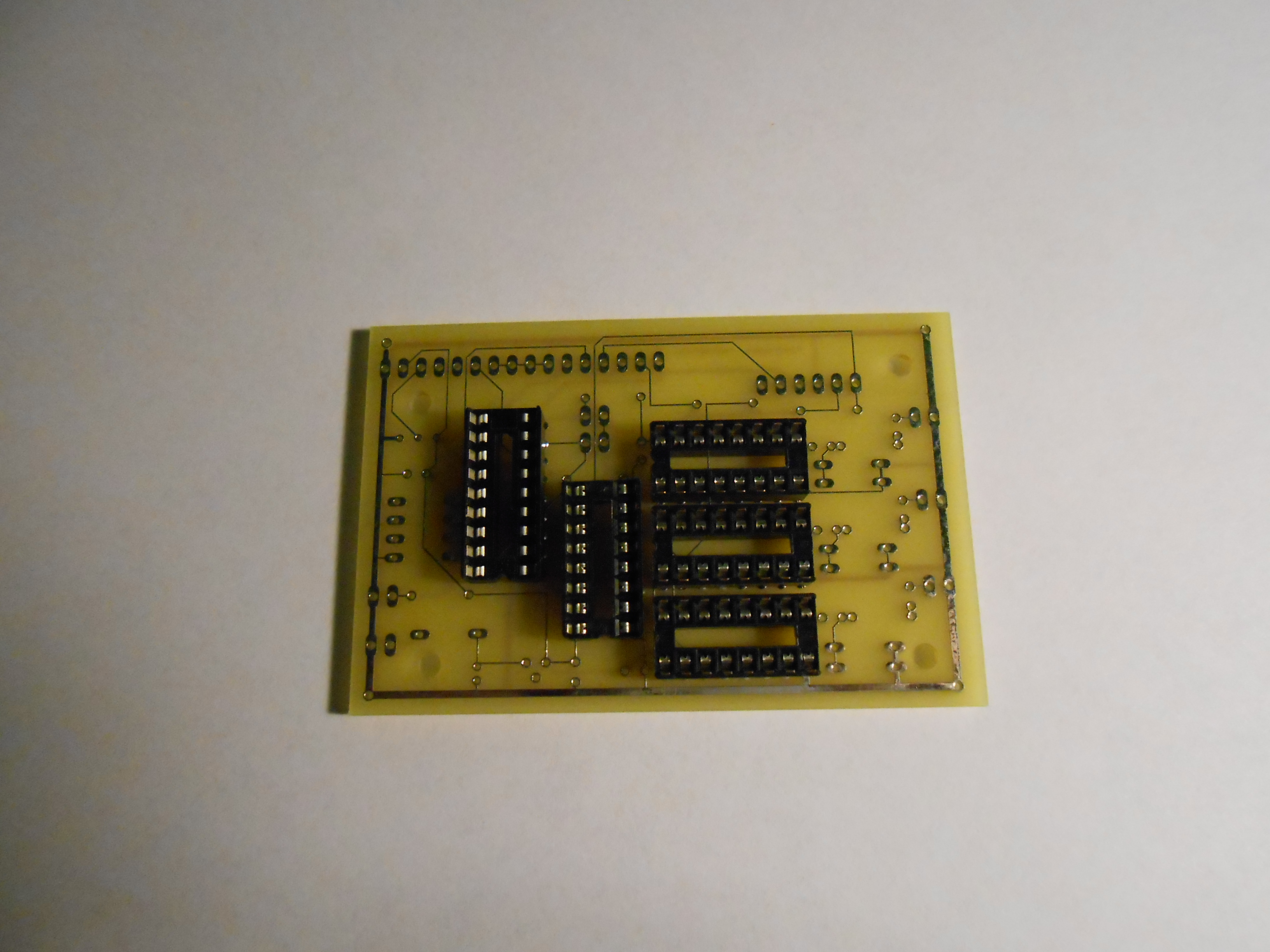
3) Install three (3) 16 pin
sockets
for the HFO, VFO and BFO (CD74HC4046).
The
notches point towards the inside
of
the P/C board. Solder
carefully. Follow
the silkscreen
patterns.
- Mouser
649-DILB16P223TLF -
(3
required) - $1.53 -
total
- Mouser
649-DILB16P223TLF
-
(1 required)
-
$.51 - total
5) Install the 18 pin IC socket for
the PIC16F628A
microprocessor with the notch
pointing toward the bottom
of the board.
- Mouser - 649-DILB18P223TLF
- (1 required)
-
$.45 - total
6)
Install
the (9) .1mf ceramic capacitors.
(C2, C3, C4, C5, C9, C10, C12, C13, C14 )
- Mouser
FA18X8R1E104KNU00
- (9 required)
-
$1.82 - total - (Mouser discounts purchases over 10 units, so order 10 units)
7) Install C6,
C7, C8 -.01
mf ceramic capacitors, 80-C324C103K3G5TA
- Mouser
80-C324C103K3G5TA - (3 required)
-
$1.62 - total
8) Install the (6) 1N4148 input protection clamping
diodes
(component
names not marked on board) for
the HFO, VFO and BFO
- Mouser
512-1N4148 -
(6 required) - $.60 -
total
9) Install R1 (100 ohms),
R2 (1K ohms) and 3 (1K ohms) - all
1/4 watt resistors).
- Mouser
MF1/4DCT52R1000F2
(1 required)
-
$.14 - total
- Mouser
660-MF1/4DCT26A1001F (2 required)
- $.28
- total
Note: If you are building the display for the FT-101, use 100 ohm resistirs for R2 and '3'.
Also Note:
R3
on the PCB is not used in this design so you'll have to jumper it with
a 30 gauge wire (may already have been done - please check).
10) Install the polarity
reversal protective diode D7 (1N4001,
or equiv),
- Mouser
583-1N4001-B
(1 required)
-
$.21 - total
11) Install C1, C11- 10
mf elecrolytic
capacitors (watch
the polarity and soldered connection spacing),
- Mouser 232-25TWL10MEFC5X7
(2 required)
-
$.68 - total
12) Install the 5 volt
voltage regulator (LM7805) - IC-7
- Mouser
926-LM7805CT/NOPB (1 required)
- $1.74
- total
13) INITIAL
POWER TEST - Apply 13 VDC to the power connector
and
verify that +5 VDC is present on pin 14 of the microprocessor socket,
on pins
15 and 16 of the CD74HC153 socket, and on pins 16 and 3 of
each
CD74HC4046 socket. REMOVE
THE POWER and verify that ground is present on pin 5
of
the microprocessor, on pins 1, 8, 10, 11, 12, 13 of the CD 74HC153, and
on pin 8 of each CD74HC4046 socket. Leave the power off until step 17.
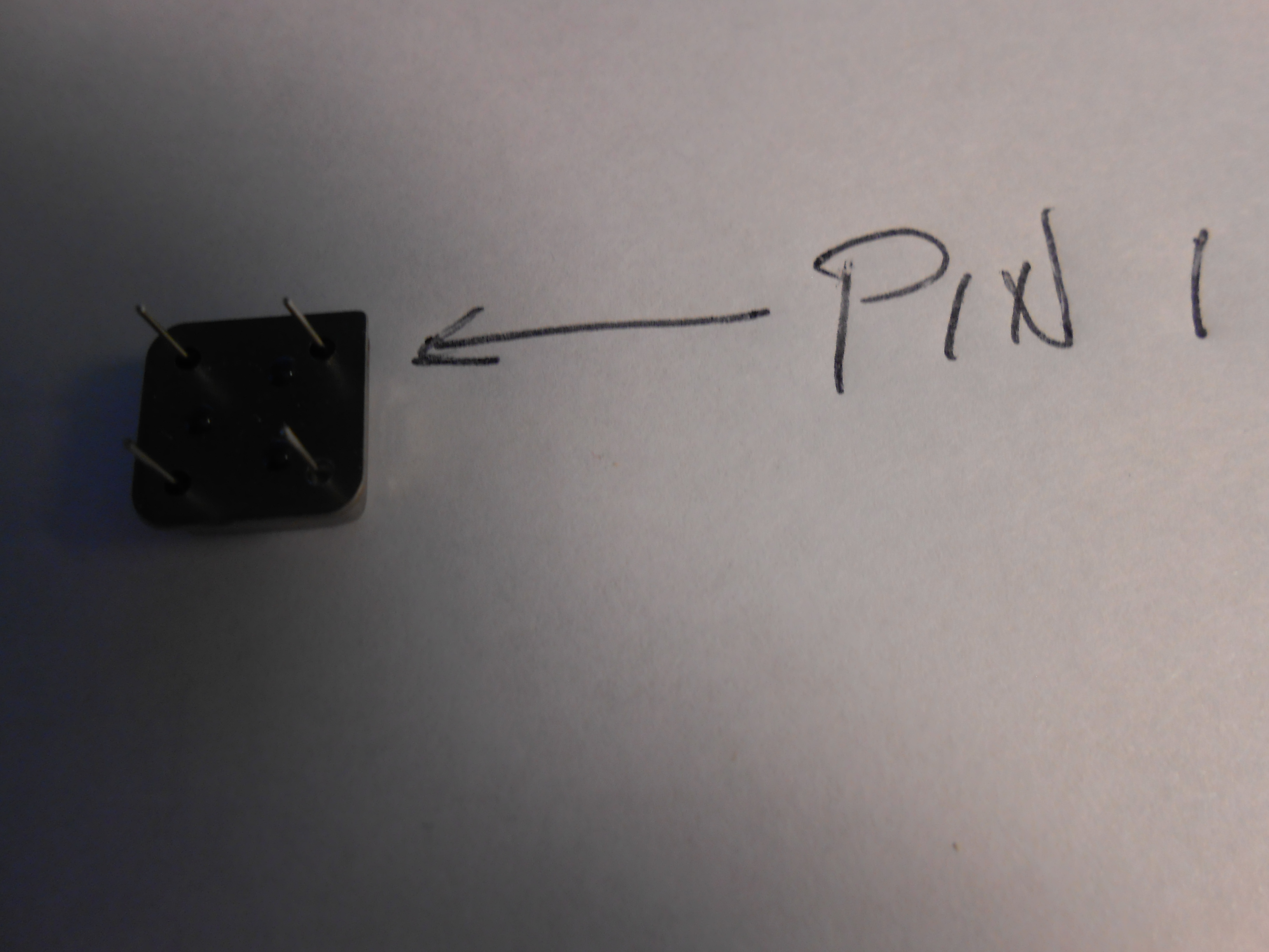
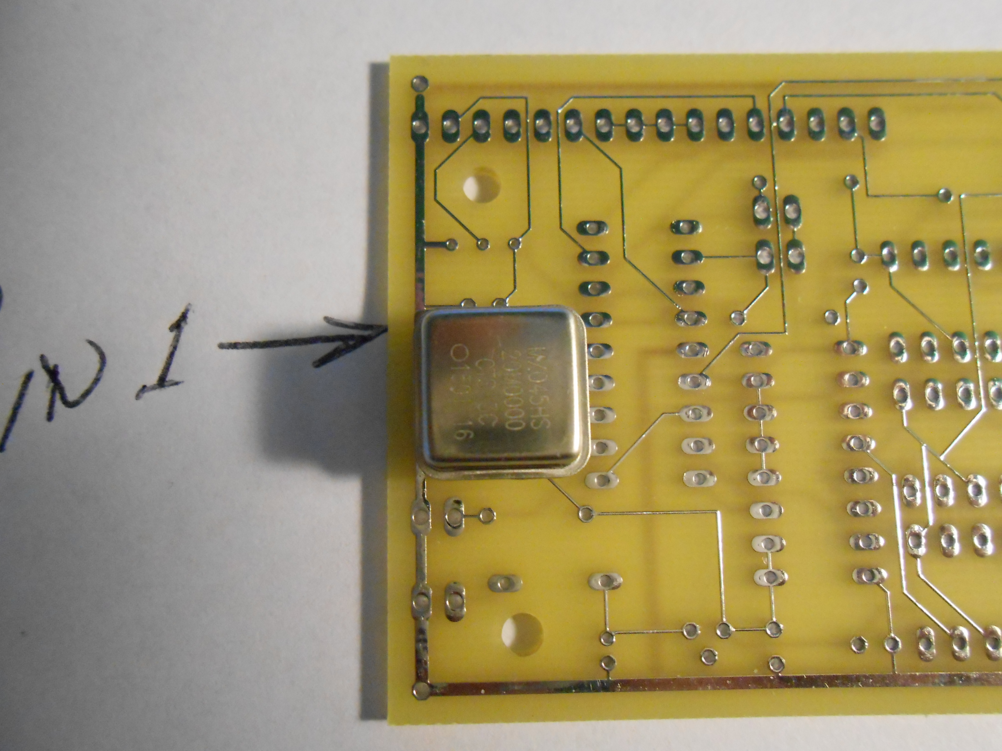
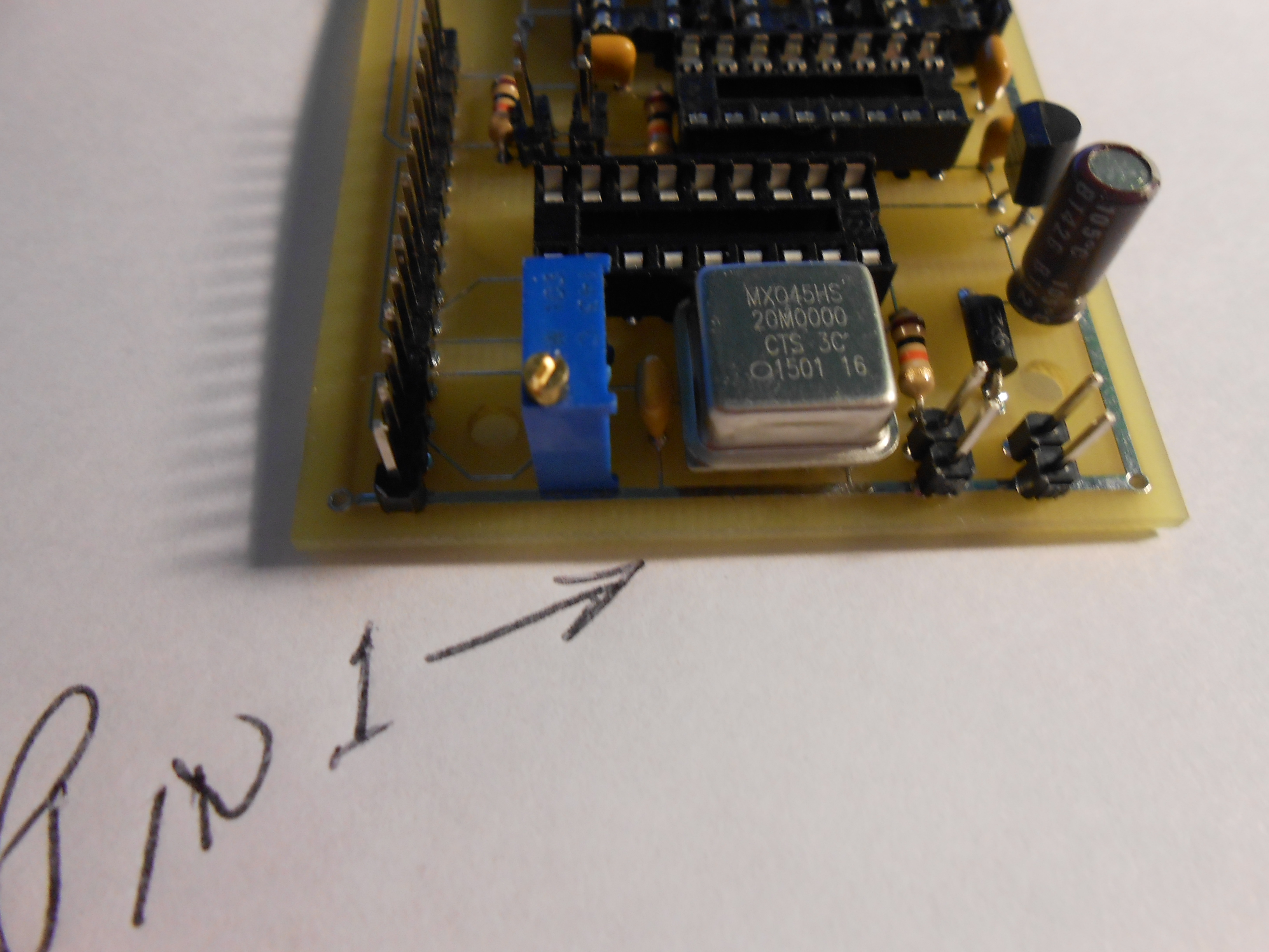
14) Install the 4 pin
'canned' crystal oscillator
(Mouser - 520-2200BX-200
).
This is a 4 pin DIP and it must be properly
installed. Pin #1 of the oscillator has a pointed edge.
Here
are some pictures showing how to orient the package before soldering it
-
pin1_1
pin1-2
pin1_3.
- Mouser
520-2200BX-200
(1 required)
- $1.94
- total
15)
Referring to the printed
circuit board layout, install the integrated circuits by
straightening the pins (rolling
them on a hard surface) and then my 'rocking' them
in.....noting their orientation. If you encounter
any resistance check it out before proceeding.
New integrated circuit sockets
sometimes offer insertion resistance the first time they are used
(like prom night?).
- CD74HC153 -
Mouser
- 595-CD74HC153E
(1 required)
-
$.84 total
- CD74HC4046
- Mouser
- 595-CD74HC4046AE
(3 required)
- $2.64 total
- PIC16F628A
- provided in your kit.
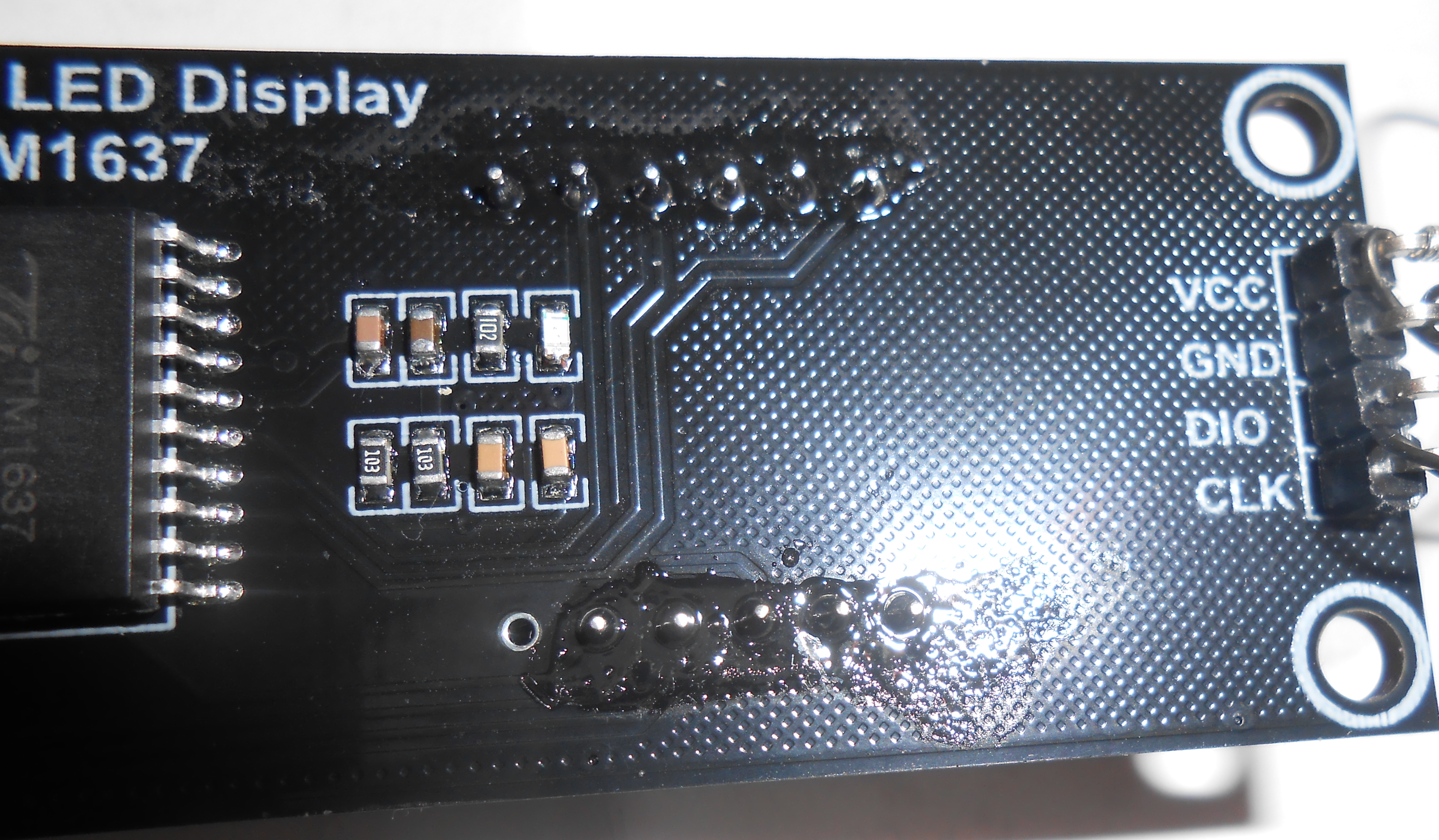
16) Wire the
6 Digit LED
Display (available
on eBay, Amazon.com and Walmart for under $10).
Pick your
desired color and be sure it has a TM-1637 serial controller.
They
come with a 4 pin wire wrap connector that must be soldered to their
backplane,
as shown here.
Four (4) connections need to be made for Power VCC (+5VDC),
Ground
(GND), Digital I/O (DIO) and Clock (CLK) - as shown in the
schematic.
Double check to ensure that you have made the right
connections (especially VCC and
GND) before
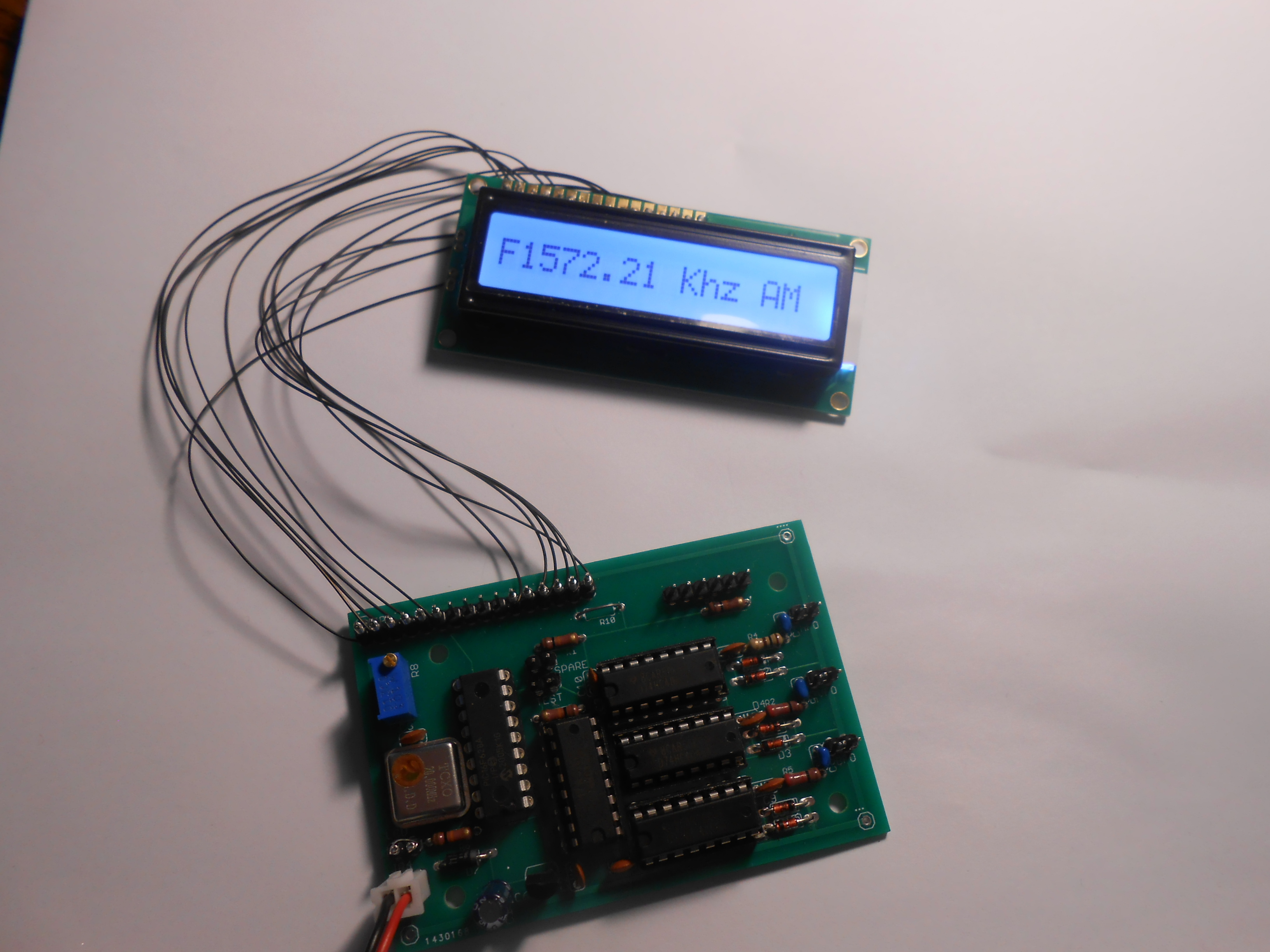
powering it up.17) Power
up your board. Since it will not be connected to a radio,
you'll see a negative number similar to
F1572.22
. until the display
has been connected to your radio's HFO, BFO and VFO points.
If
you find that the display is too bright for your liking (most probably
only on WHITE displays), you may tone it down a bit by
shorting the DIM
pins on the board. Since
the unit has been programmed to
update the display ONLY WHEN the received FREQUENCY HAS CHANGED, you
may not see the display change immediately.
Using 2 to 3 foot lengths of RG-174 (or
equivalent), install
PHONO plugs on one end and and solder the other end to
the HFO, VFO and
BFO
DDS VFO P/C board connection points. Either tag or color code
these
connections and insert them into the SB-300, SB-301, SB-303
(etc). Jacks are on the radio's rear panel. These are the easiest interfaces.
Note: For
the SB-303 place a 47 ohm resistor across
the VFO
coax connection from the radio to the DFD-2. If this
resistor is not
placed, the frequency display may become
intermittent.
The Kenwood TS-520S HFO, VFO and BFO
plug-in connections are on the rear panel ( rear mounted jacks).
Power (12VDC) can be suppiled via an inexpensive wall-wart and / or is
available from the radio itself (TS-520S)
Good luck
on
finding the original GD-5 plug that powered the Kenwood DG-5 digital
display.
Small female jacks can readily be installed on the TS-520S
rear
panel to provide a source of fused 12VDC for your counter - just attach
the lead to the DG-5 connection points.
5.
Heath SB-100 / 101 / 102 / HW-100 / 101
CAUTION: - if you
are unsure, unfamiliar or unable to work safely within a tube
radio where potentially lethal voltages lurk, please don't
consider this product unless you have a competent and
experienced helper with you. I
will not be responsible for any harm to either you or to your radio as
a result of attempting this conversion. If you
have any doubts - don't
try it or check with your 'Elmer'.
- All connections are made at the cathodes of the various
oscillator tubes.
- All
connections are made through a 27pF cap (at least 50 DVC) and RG-174
coax. 27
pf
was found to provide adequate coupling without loading any stage.
- HFO connection at pin 7 of V11
- VFO connection at pin 7 of V12
- BFO connection at pin 9 of V13
- Bypass (Jumper out) the input .01 and the 1 K resistor on
the HFO input circuit of the counter if it will not count above 15
meters.
- Keep cables as short as possible.
6.
Heath HR-1680
7. Heath SB-104(A)
Not Required! - an
inexpensive 6 Digit Digital Frequency Counter available on
eBay can nicely fulfill this need
8. FT-101 Radio Family
Interface - self contained and
ALWAYS accurately reflects
the CLARIFIER, BANDSWITCH, VFO and MODE settings! - New!
a) The DFD-2 - A Proven Design Helpful in Several Radios
Neil Hecht (a genius and now sadly an SK) founded
www.aade.com. He cleverly designed digital displays for many of
contemporary analog radios including the DFD-2 solution for the Heath
SB series and many other rigs. I used the essence of his
hardware design and wrote my own hand assembled code not only for my
original DFD-2 (both LCD and 6 digit LED interfaces) but also for the
FT-101 version. This required some significant changes to acommodate the
FT-101
frequency conversion scheme. The software simply reads,
'massages' and outputs an accurate digital display only when the
computed frequency actually changes. This way, needless circuit
noise is eliminated.
The Heathkit (SB-300 / 301 / 303) and Kenwood (TS-520S / SE) radio
designers provided rear mounted HFO, BFO and VFO signal pick-off points
and are therefore eminently easy to connect to the DFD-2. Yaesu
did not
do the same as they apparently had no plans to equip their radios with
digital displays 'back in the day', mainly because (I assume) popular,
easily programmed processors like the Microchip PIC and
Freescale's HC05 / 8 series were not available then. Heath used
them to
provide
true transceive operation with their matching SSB transmitters (SB-400
/ 401) and Kenwood was apparently more foresighted with a true,
outboard digital display in mind.
On his website
(search the Wayback Machine) Neil offered plans to interface his
DFD-2 design with the Yaesu FT-101 series. Iinterfacing the DFD-2 to an
FT-101 is a bit move involved as
RG-174
miniature coaxial cable needs to be run withn
the radio to the circuit
boards providing the VFO, HFO and BFO (Carrier Oscillator) signals.
Each lead is connected to the points shown below through a
small
capacitor (values stated later) and then run to the rear panel for
connection to the DFD-2
proper.. Three signals (HFO, BFO and VFO)
need to be routed to the DFD-2
unit itself.
b) Connecting the DFD-2 to the FT-101 Radio - Two Options
These
signals can be 'picked' off points on various circuit boards and then
run to connection points on the FT-101's rear panel. Ideally,
one
would try to find spare chassis space in which to drill the holes,
install the jacks and terminale the RG-174 coaxial cables. Howeve
the FT-101 is built very compactly and exactingly and
spare areas
are sparse indeed. But, if you are clever - and determined -
you can do it! Here are some posible connection options along
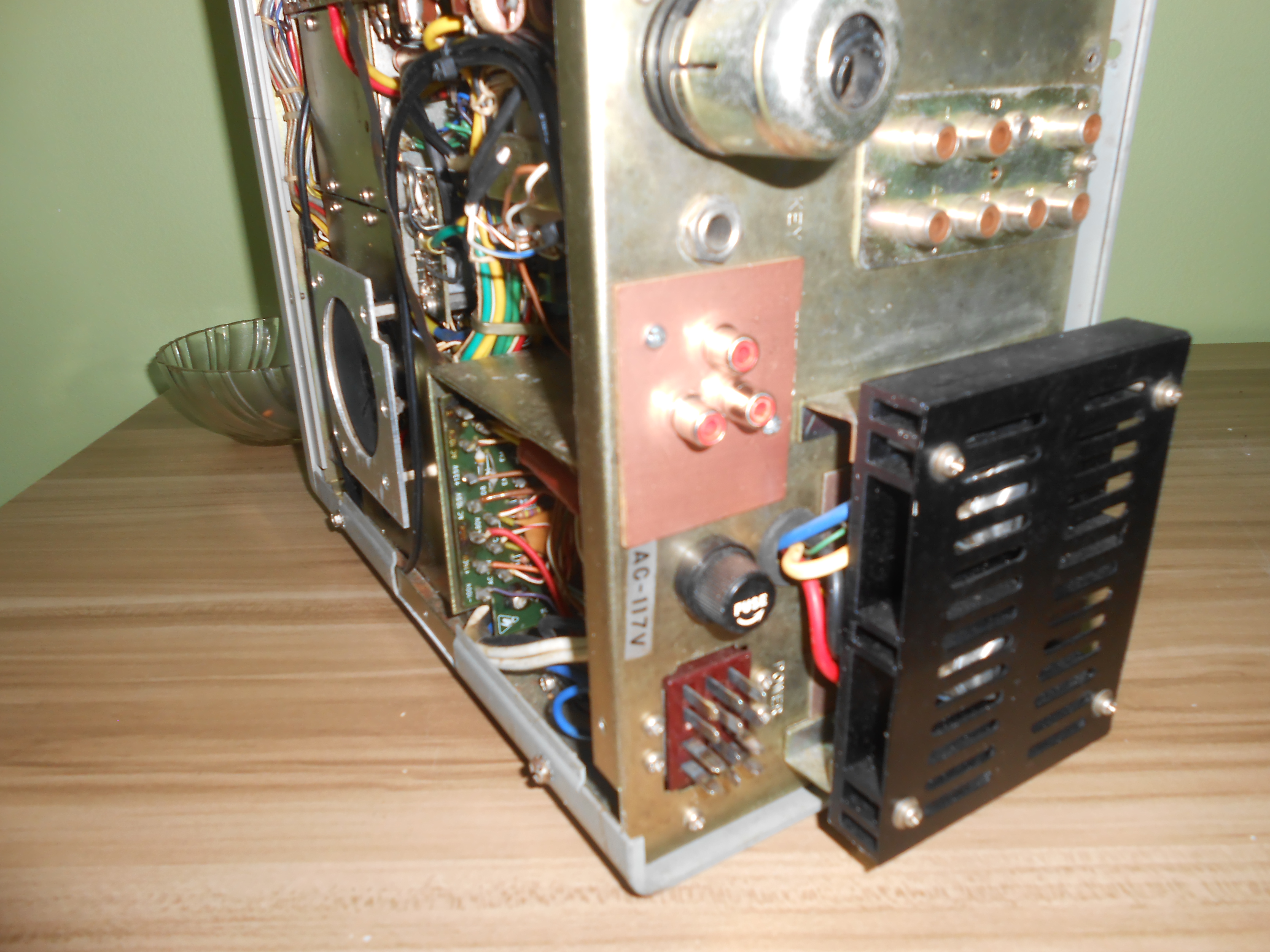
with the one that I used::- Repurposing the Existing Rear Jacks - PROBABLY THE SIMPLEST APPROACH -
One approach might be
'repurposing' 3 of the existing RCA jacks in
the center rear of the radio. I initially did not consider this
method as (I thought) some of the FT-101 users whould feel that it
would diminish the retail value of their radio. However. I
believe that I was wrong in this regard and if I converted another
FT-101 I'd use the existing jacks and their ground lugs this time.
For openers, the RCA type jacks are already there and no extra
holes need to be drilled nor anything else done to the rear panel.
It will look completely stock after the conversion. The
jack panel is easily opened up and the jacks that one does not plan to
use can be readily disconnected from the internal wiring. There's
an existing (grommeted) hole in the chassis thru which the coax
connections can be run. I think this a 'slam dunk' method and
would encourage any readers to thoroughly consider it. It will make the conversion much easier.
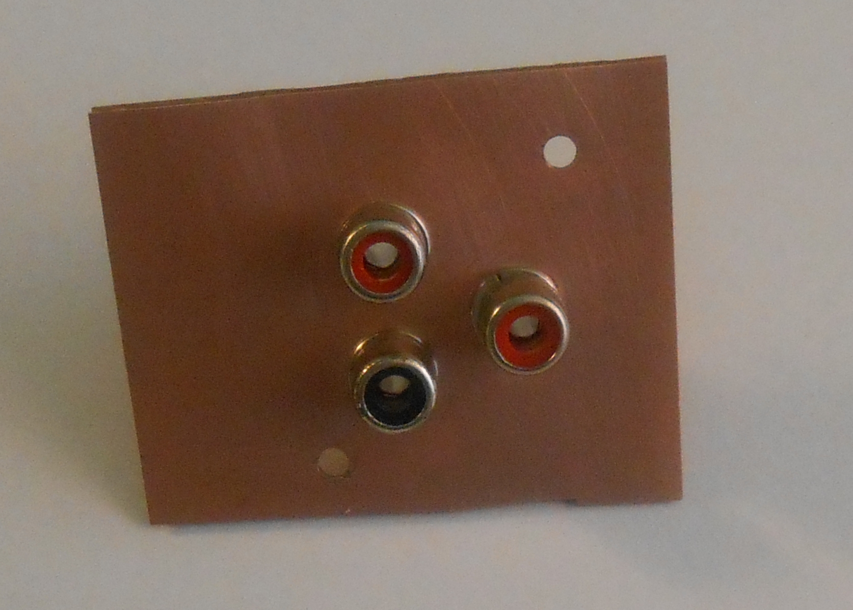
- Repurposing the External VFO Connector -
Although
the original 8 pin VFO socket could theoretically be used, I
tried several times to connect the HFO, VFO and BFO outputs to it
grounding each of their shields to a common ground. It didn't
work! So, I removed the socket entirely, removed the 2
short pieces of coax
for the external VFO and insulated the 3 wire leads running to it.
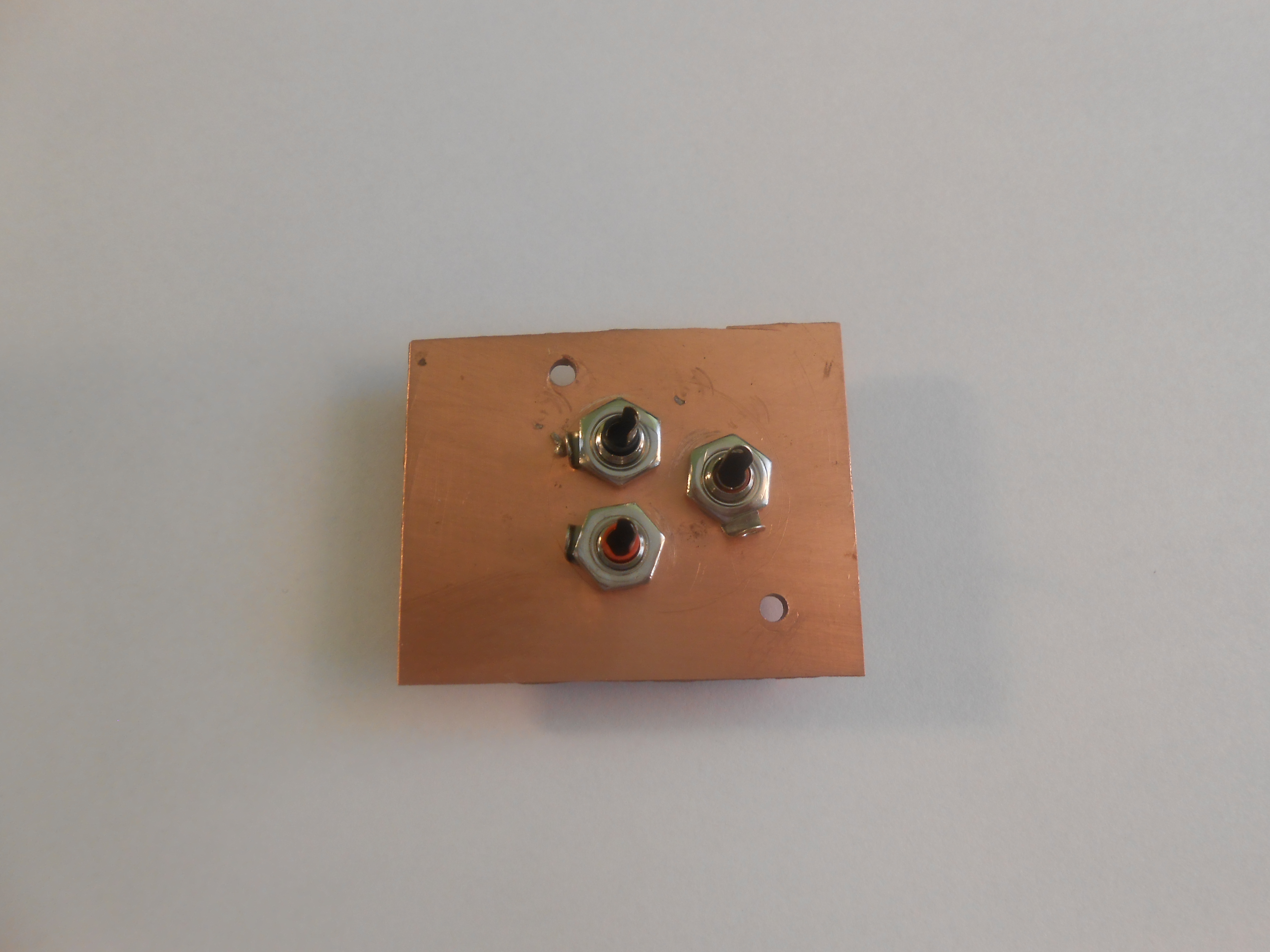
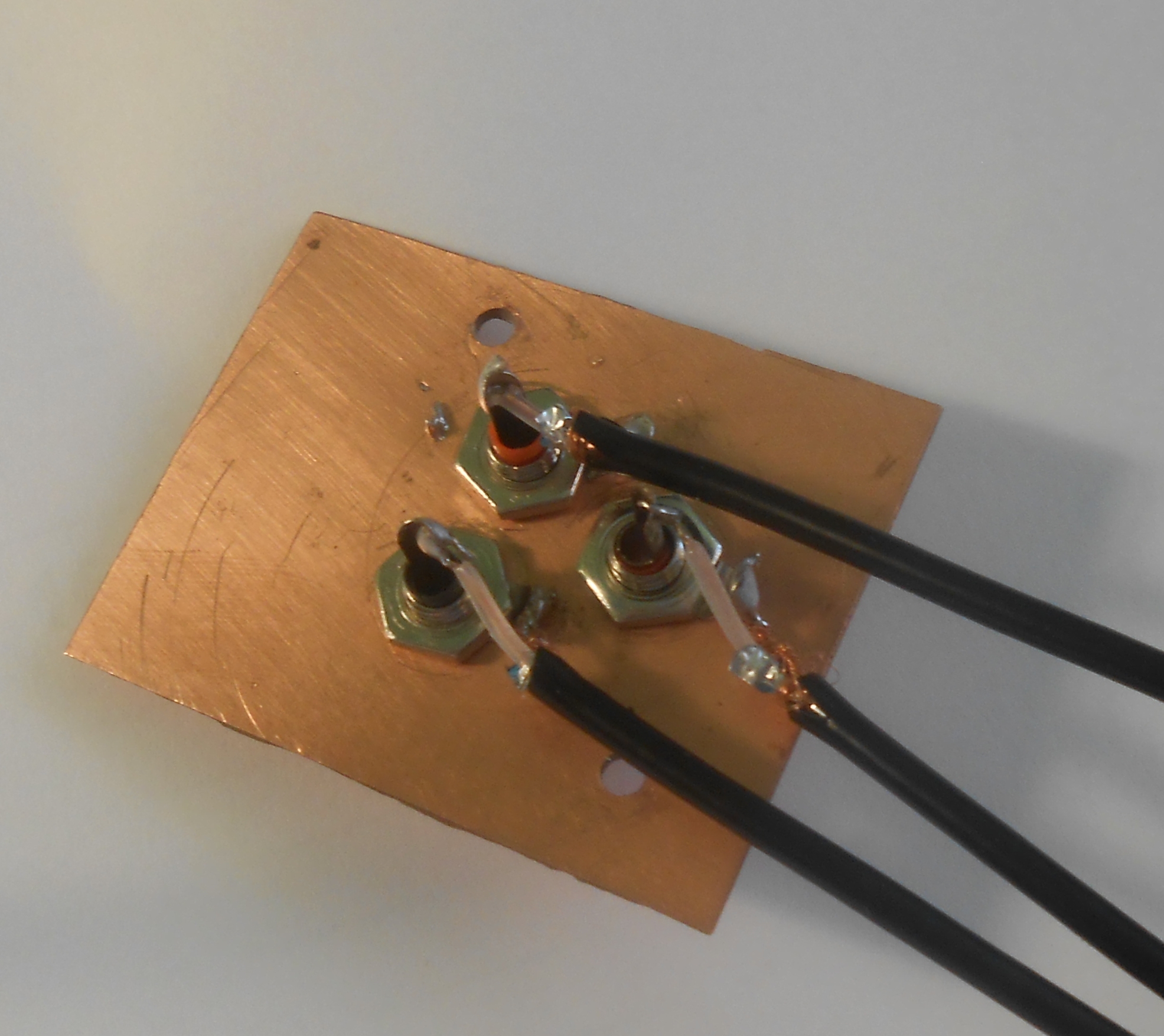
I replaced it with a small piece of grounded printed citcuit
board materail on which 3 RCA phono jacks (with ground lugs) had been
mounted. These would become the connection points
for
the HFO, BFO and VFO. I prepared 2 foot lengths of RG-174 with a
male
plug soldered to each end and these would be used to connect the
display proper If you decide to do your coversion this way you
need to be sure that the RCA jacks are securely tightened to thie piece
of metaal or printed circuit board. It's suggested that the 3
lengths of RG-174 coax be measured and connected before the board is
actually mounted.
- Note: if you opt to remove the octal plug you'll find the
following wires on it: Pins 1 and 8 have ground, and they can be
just cut off. Pins 6 and 7 have the paralled coax connections and
shield groindsfor the external VFO siignal. They can likewise be
removed.. The other wires can likewise be turned back and
individually insulated (heat shrink tubing). The brown wire - however - needs to be reconnected and insulated with heat shrink tubing
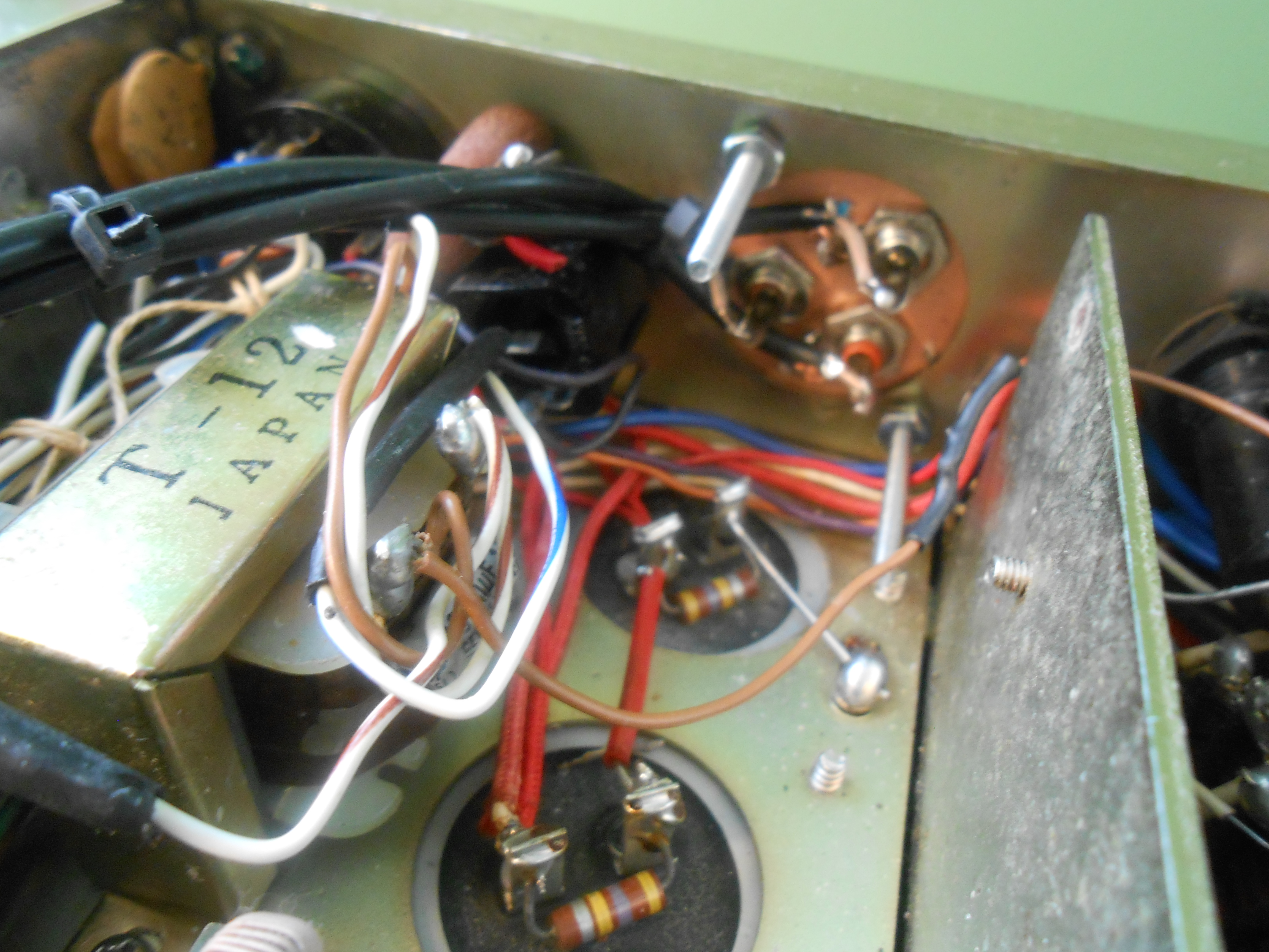
- Picking Off THe HFO, BFO and VFO Signals
- The BFO
signal may be
tapped underneath the chassis on pin 5 of
board 1183A (LOW FREQUENCY IF BOARD). Solder a
100pf disk ceramic capacitor to
the center conductor of the cable and solder the shield to a nearby
ground.
- The HFO signal
is available at the test point
near the top edge of board 1181A - (HF UNIT)
- install the coupling capacitor (100 pf disk
ceramic) on the board between the test point and connect another piece
of RG-174 to the other side of the capacitor, carefully ground the
shield to the outer ground trace of the plug-in board and then route the
coax from the top of the chassis down thru the VFO enclosure to the rear RCA phono jacks mounted where the VFO 8 pin plug used
to be. Be sure to leave enough slack in the coax so that the
HFO
board may be removed for servicing should the need arise whithot having
to disconnect the connection under the radio.
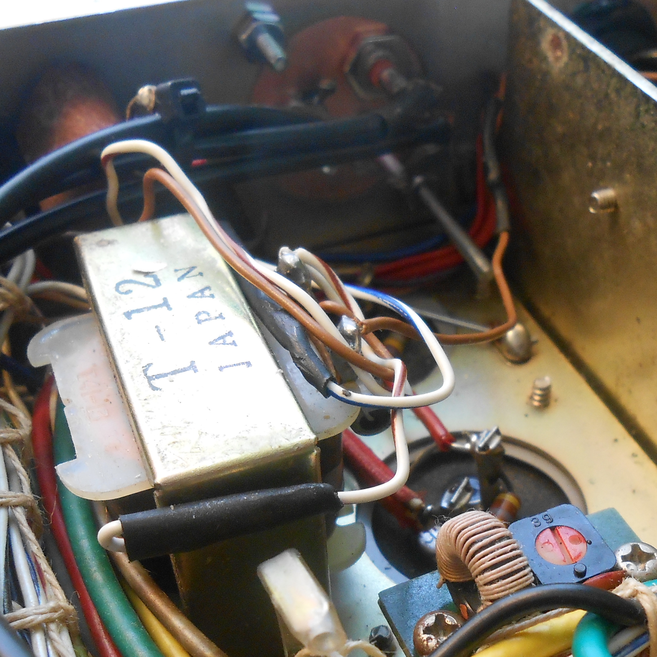
- The VFO
signal is connected where the original 2 coax cables for
the external VFO were connected..
After routing the cable from the rear of the chassis and connect it
directly to the respective RCA jack. No decoupling capacitoor
is
required.
Note: Tag
the rear panel connections after you have made them. If you
forget which is which, just turn the radio on and measure the
output of each with your digital meter or a suitable freqjuency
counter. The
- HFO output
will follow the setting of the
bandswitch, the
- BFO will be in the range of
3.1 Mhz, and the
- VFO will - of course - follow the setting oh the VFO tuning knob around
8 or 9 Mhz.
c) Assembling the DFD-2 Circuit Board
Note:
Before starting with the conversion it's advisable to ensure that your
FT-101 is working properly. Especially check the 6 volt source
and the frequwncy setting trimmers on the modulator board for accuracy.
Follow the instructions on this webpage to build the DFD-2 board
itself. All the parts are listed with the latest parts and a
Mouser Electronics parts list (see above). The only changes are
that the input resistors for the VFO and BFO are changed from 1K to 100
ohms.
This reduces any unnecessary loading on the FT-101's BFO
and VFO circuitry. Soon, I'll make both the PCB and pre-programmed
PIC16F628A processor available for purchase. At this point I don't think I'll be sellain any fully assembled ujnits.
I mounted my PCB in an aluminum box
purchased on Amazon. I drilled 2 holes and used the box as a heat
sink for the LM-7805 voltage regulator. A piece of plexiglass
(Lowes) with some carefully cut black tape serves as the front to which
the 6 digit LED display is affixed on the inside. Others with
more
mechanical dexterity that I possess or those who may have access to a
laser printer could undoubtedly do a better job.
d) Display Power Supply Considerations
I had originally planned to use a power cource within the FT-101 for
the display but was later reluctant to use the 12 VAC filament winding
as a source of AC for a new, inboard internal DC rectifier.. So,
I
used a wallwart yype device. I you go this route you might try to
find a wall wart that uses a transformer driven one as these are more
electrically
'quiet'.
e) Operational Aspects
- Power Up - If you activate the display before turning the FT-101 on you may notice
a (very) brief display (like F9xxxx).. This is because the
firmware in the display needs a second or two to synchronize with the
radio proper. Don't be alarmed. Also,just after switching
bands or modes there will be a very slight tbefore the display
updates. After that - however - you'll find the display quite
responsive.
- Mode / Band / Dial Frequency Updates -
the display will compute the actual frequency depending upon the
position of the mode switch, but not immediately. This is because
of the way that the software was written. For exzample, when
switching sideband modes, there can be a 2 to 3 second delay before the
proper frequency is displayed. The same is true of whenever the
band switch is rotated. All the other DFD-2 applications for the
Heathkit, Kenwood and Drake radios work the same way. The actual
frequency display (including Clarifier chganges) - however is nearly
instantaneous as the frequency is scanned 4 times a second. No
attempt is m ade to update the 6 digit LED display unless the computed
frequency actually changes. This helps to ameliorate or eliminate
any possible electrical noise.
- Transmitting
- when first transmitting, the display will shift a bit off frequency
and then settle down where it should be. This 'blip' is because the
processor is scanning and displaying 4 times a second and willl 'see'
the FT-101 shifting from receive to transmit. There's a brief
'unguareede' interval here that could only be prevented by
additional software and another connection between the display board
and the FT-101 proper. The same 'blip' may occur when going from
transmit to receive - for the same reason. The DFD-2 in the
Heathkit and Kenwood environments work the exact same way.
f) Other Considerations
- Creeping Frequency Changes - after first connecting the display to the radio the display would - very infrequentht
- start to creep. At first I thought this had to do with normal
oscillator warm up drift which will happen for a couple of minutes
after the radio is first turned on. However, the problem turns
out to be the open trimmer resistors tha Yaesu used in this radio, most
notably the CLARIFIER (behind the Clarifier control) and the ZERO
(Power Regulator Board)trimmer. THey should be thoroughly cleaned
- Replace the 6 volt adjustable voltage fregulator with an LM-7806
Birdies
Even radios designed with integral digital displays will evidence some
birdies and artifacts when not connected to an antenna and this
conversion is similar in that regard. However, with an antenna
connected and the preselector properly tuned the only birdie I've
noticed is around 14.167. If I have the time I'll see if I can
track down the source.
9.
Enclosure Suggestions
Selecting a suitable, functional and
reasonably attractive enclosure is a matter of personal choice and
handcrafting ability. I'm not terribly dextrous when it comes
to
ccrafting items like this one, but I did build a couple of enclosures
whose details I'll share with you.
For one
enclosure for a TS-520S, I used a small
plastic clamshell type of enclosure found on eBay. I used a
piece
of plexiglass (Lowes) as the front panel and mounted the 6 digit LED
unit on its rear - looked reasonably OK. Since it was physically light,
I added a couple of flat electrical box covers
(from Lowes) inside to both weigh it down (so it would not
move on my desk) and to provide a heat sink for the voltage
regulator.
The regulator does not get all that hot, but inasmuch as I
had
installed the flat electrical box covers beneath the board for weight I
decoded to use it as a 'sink'. I had some spacers from
another
radio that I had cannibalized, so I used those. (Simple 4-40
machine screws, washers and nuts would have worked just as well.)
The
6 digit LED is mounted on the front along with an OFF - ON power
switch. The power connector, 3 RCA inputs and an optional
switch
to activate the counter feature are located on the rear
panel.
I put sticky feet on the bottom. I'm sure that
those of you
with better mechanical skills could whip up something a lot nicer.
For another enclosure (for the FT-101) I used a small metal
clamshell enclosure from Amazon. It has metal covers on the
front
and rear.
I cut a piece of plexiglass to serve as the front cover
and carefully drilled holes in the 4 corneers to match up with he
openings in the cabinet. The LED display itself mounts on the
inside of the plexiglass held in place by 2 flat-head screws drilled
thru to the plexiglass. The printed circuit board is
mounted on
spacers within
the box which is also used as a (rather generous) heat
sink. A couple of ventilation holes were drilled in the
botton
and top. Stick-on rubber feet keep it stable on top of the radio or on
the operating desk. Since the box is heavy metal, there's no
need
to weigh it down.
Also, Mouser sells some interesting enclosures that would
also fit the
bill. Here's just one series:
http://www.busboard.com/documents/datasheets/BPS-DAT-(BOX2-P14)-Datasheet.pdf
You'll want to get one that has removable front and rear
covers.
10.
Radio Service Manuals & Schematics
Copyright
2020 thru 2025 - - K3JLS - All Rights Reserved - Software and
PCB Design Included