Host your Web site with iPage!
Converting a Wideband Phoenix VHF /
UHF Unit for Ham Band Use
With Integral CTCSS Encoding / Decoding
(Click Here for the Legacy External
MX-COM 465P Conversion)
New!
- Phoenix Service Manuals (Thanks to Kevin Custer - W3KKC
- of the
Repeater Builder's Group for this courtesy):
1.
Introduction
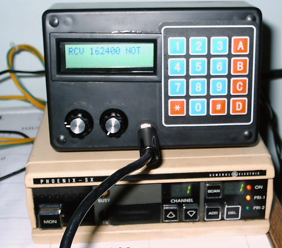
The Phoenix units are easy to
convert as an
external control head with volume and squelch controls need not be
built. The radio comes equipped with a volume control and (with some
models) an internal speaker. Before starting the conversion,
it's
suggested that you read the instructions through to the end.
You
may email me with any
questions / suggestions.
The Phoenix radio can be converted for frequency agile operation in one
of two ways:
- Local
Conversion
- The external M/P, keypad, and LCD display can be mounted in an
enclosure and then connected to the Phoenix with a DB-25 cable.
The Phoenix microphone connection and the ON/OFF
switch and volume control functions remain intact. Both the
radio
and the control head must be within easy reach of
the driver.
- Remote
Conversion - A more
conventional Control Head containing
the volume control, speaker, mike jack, remote power switch - the radio
itself may be mounted in some out-of-the-way place in
your car.
2.
Preparatory Steps - Schematic
- Secure a technical manual for the radio or check the
on-line material (links above).
- You'll
need a power connector (P-910). If you don't have this
connector,
then solder the power leads to J-910, as shown.
- The positive
(red - always on) high current 12 volt lead connects to J-910,
pin 11.
Provide a 15 amp fuse in this lead.
- The negative (black) lead connects to J-910, pin 6, 7 or
8 (they're all common
chassis grounds).
- The positive (switched) low currect 12 volt lead connects
to J-910,
pin 1 (see attached). Provide a 2 amp fuse in this lead.
- After
making the power connections, check to
see that the receiver audio works (by
breaking the squelch and / or by listening to a station).
Transmit into a dummy load. If your radio has a
programmed 2212
EEPROM chip, your conversion
will ignore the programmed frequencies and Tone Squelch (CTCSS) values,
but will be be controlled by the Carrier Control Timer (CCT) length
stored therein. If the CCT value suits your operaring
preferences, then you're all set. If not, you will
have to
reprogram the chip. This chip is
needed for the conversion to work.
- Next, decide how you want your conversion
to work. You
can either retain the microphone, volume control and power (On/Off)
within the Phoenix, or remote these functions (along with the M/P, LCD,
Keypad, etc) to the control head. Instructions are provided
for
both techniques.
3. Steps Common to Both
Conversions -
Complete These First
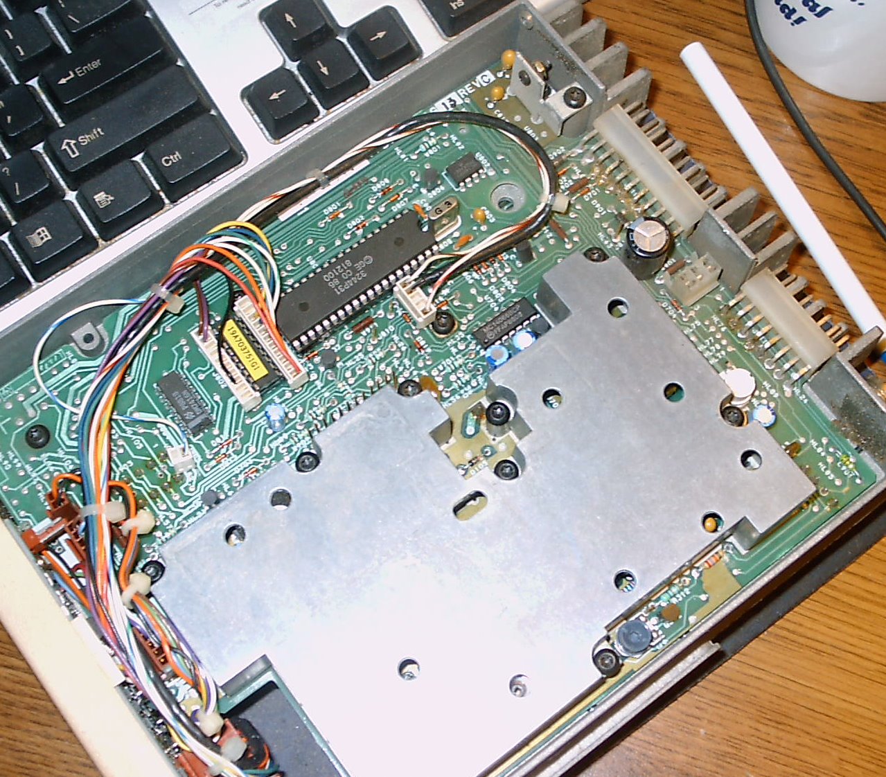
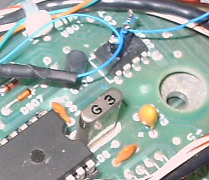
- Remove the top cover of the radio
(internal 40 pin M/P will visible). Here's a sketch
of the key components.
- On
J-910,
place a 30 gauge wire from pin 9 (CG DISABLE) to pin 6
(GROUND). This disables the Phoenix' internal CTCSS
circuitry, ensuring that the Phoenix will not send any CTCSS
signals in the transmit mode which will interfere the CTCSS signals
generated by the external M/P.
- Clip either side of diode
D819, opening the squelch when
carrier is detected.
- Cut
the male end off a 25 pin DB-25 cable and remove about 12 inches of the
insulation. You're going to use the Female end
for your
conversion:
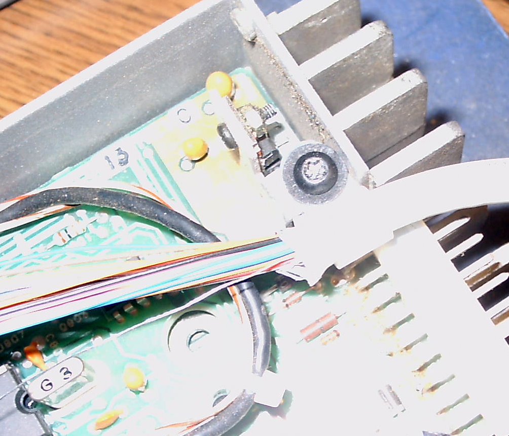
- Important
Note: Cable clamps will also serve to elevate
the conductive
ferrite beads above the P/C board.
- Five
(5) leads (7, 12, 16, 21,
and 22) and the shield wire
are connected together for a robust ground
connection.
Identify them with your meter and solder them together with
some
heat shrink tubing. Then run this common lead
to J-910, pin 6.
- For an external
speaker, connect DB-25 pins 19 and 20 to
J-910, pins 3 and 7 (either way). If not, bundle these leads
together with the other spare or reserved leads.
- Connect DB-25, pin 2 - the COR lead
- to J-910, pin 2.
- Connect DB-25 pin 1, the Mike PTT
lead, to J-911 pin 2. Use 2 ferrite
beads.
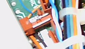
- Connect DB-25 pin 18, the CTCSS OUT
lead to the input of the + side of C-718. Use 2 ferrite
beads. There is access to this pin on the topside of the
Phoenix board (upper right corner).
- Connect DB-25 pin 2 - the CTCSS RCV
lead to U-801 (M/P) - Pin 29.
- Carefully remove the Phoenix' M/P from
its socket and bend pins 8, 10, 19 and 33 outwards so that they will
not contact when the M/P is re-inserted into its socket - but
don't replace it just yet.
- Using an ohm meter, verify the following existing P/C board
connections:
- Internal M/P pin #8 (Enable), and to
U-804, pin 13.
- Internal M/P pin #10 (Clock) to U-804, pin
9,
- Internal M/P pin #19 (Data) to U-804, pin 5,
and
- Internal M/P pin #33 (Channel Change) to U-804, pin #11.
- Tack solder the DB-25 leads shown below to their respective
pins U-804, connecting them (with 2 ferrite
beads on each):
- DB-25 pin 15 - Enable Lead
to U-804 pin 13,
- DB-25 pin 13 - Clock Lead
to U-804 pin 9,
- DB-25 pin 10 - Data Lead
to U-804 pin 5,
- DB-25 pin 14 - Channel Change
to U-804 pin 11.
- When done, place a dollup of hot glue on the top of U-804
to hold these leads in place.
- Replace the internal M/P back into its socket with the
proper orientation, ensuring that the bent pins do not touch their
socket pins, nor anything else.
- Place a small, 30 gauge jumper between the pin 19 (that you bent out from U-801,
the M/P)
to pin #1 of the EEPROM. This jumper can be wire wrapped to
the
pin adjacent to pin 1 of the EEPROM chip. This ensures that the
Phoenix M/P can access the CCT data.
- Tack
solder a 30 gauge wire to U-801 (M/P) - Pin 27 and run it to the
collector of QS,
a 2N3904 NPN transistor. Connect
the emitter to ground. Connect RS,
a 10K current limiting resistor
to transistor base, and then run a 30 gauge lead from the other side of
the 10K resistor to the 'hot' side of the panel mounted BUSY
lamp (here's the schematic). Epoxy the transistor in some
convenient place, 'dead bug' style. This switch ensures
that the receiver's audio will ALWAYS
open up after
reverting back from the transmit
mode - provided there is a squelch breaking signal present.
- (Probably not needed) - Tack
solder DB-25, lead 6 to U-801 (M/P) - Pin 6 on the top side of the
board, and place 2
ferrite beads . This alerts the external hardware
that the PLL is locked (if necessary
to invoke the transmit override).
It was not
required in the unit that I converted, and the lead was not connected.
- (Probably not needed)
-Tack
solder DB-25, lead 11 to U-801 (M/P) - Pin 28 on the top side of the
board, and place
2 ferrite beads. This connection may be needed to ensure
transmission, but only
when the PLL is locked. It was not required
in the unit that I converted, and the lead was not connected.
4. Local Conversion
For
this conversion method, almost everything is now done. Only
three other connections need to be made:
- Remove the other radio cover (if not already done).
- Remove
the 4 screws (and metal reinforcements) holding the front
cover
and carefully move it aside. There is no need to disconnect
any
front panel cabling, especially if you are converting a Dual Priority
Scan radio.
- Remove the setscrew holding the round volume control wheel
and the wheel itself.
- Remove the cover under the wheel exposing the volume
control potentiometer and the ON / OFF switch contacts.
- Using
your meter, identify the ON/OFF contact that provides switched DC
to
the Phoenix and solder a 30 gauge wire to it. This will be
the
power supply lead for the Control head.
- Place 2 ferrite
beads on this lead and connect it to DB-25, pin 3.
- Replace everything in the reverse order.
The two remaining connections involve the microphone. Since
the
external M/P (and not the mike) will be 'keying' the radio,
the mike PTT lead is cut and run over a DB-25 lead to
the control head. Another DB-25 lead will be required to
connect the PTT circuitry within the control head to the Phoenix.
- The
connection on J-911, pin 2 is severed between the mike
connection and the chassis so that the mike can still be
connected to J-911.
- Connect the severed PTT lead
on J-911 to PTT
Local DB-25 lead pin 23 with 2 ferrite
beads.
- Connect the severed chassis connection PTT Return
to DB-25 lead pin 24 with 2 ferrite
beads.
Note: Do not use too much heat
when soldering to the severed chassis connection as the PTT lead might
drop down and make accidental contact with the frame of the radio.
To fix this, the board itself will have to be removed.
Connect the microphone (and a speaker,
if needed) to the radio and move on to the final
adjustments.
5. Remote Conversion
The remote conversion
involves the removal of the Phoenix' volume control and ON /
OFF
switch and the installation of a remote power activation relay. These
functions will now reside within the
control head.
- Remove the other radio cover (if not already done).
- Remove
the 4 screws (and metal reinforcements) holding the front
cover
and carefully move it aside. There is no need to disconnect
any
front panel cabling, especially if you are converting a Dual Priority
Scan radio.
- Note the location of the volume
control. Remove the screw holding the adjustment wheel and
then
remove both the adjustment wheel and the cover beneath it - discard
everything. When you have removed the plastic cover,
you'll see the
potentiometer.
- Solder an 8 inch twisted pair of
18 gauge wire to the larger metal strips on either side of the
control. These are the connections to the Phoenix
ON / OFF
switch. These
connections the remote power relay and are made
before the control is removed so these leads won't fall through when
heated.
- Using a pair of diagonal cutters, sever these
metal strips above
the solder joints, leaving the wiring you just placed intact.
- Note the remaining 3 connections of the pot. One
is chassis ground; another, the center of the control and
the third is to the 'hot ' side of the control.
- Connect DB-25, pin
4 Volume
Center to the center lead of the Phoenix control.
- Connect DB-25, pin 25 Volume High
to the 'hot' lead of the Phoenix control.
Remove the volume
control by cutting these leads
above the
solder connections. The ground connection which
may be severed at the P/C board itself.
- Run the two twisted leads from the old volume control
switch up to the other side of the chassis.
- Connect DB-25
pin 9, the Mike
High lead, to J-911 pin 4. Use 2 ferrite
beads.
6. Preliminary Testing
Ensure that all connections
are correct. A test
table
provides resistance and voltage
measurements at each of the DB-25 connector pins.
- Make the resistance tests from the chassis to
each of the
pins in the DB-25 connector. Correct, as needed.
- Apply power to the Phoenix by either operating the ON / OFF
switch on
the volume control (Local Control), or by (Remote Control) grounding
the low current power relay contact DB-25 pin
17.
- Measure the voltages at each of the
pins.
- When done,
remove
the ground.
7. Connecting the Control Head
You'll have to build up a
control head, and the required
components are available. A large Radio
Shack plastic enclosure works perfectly as it can house the P/C board,
the keypad, LCD, the volume control (with an OFF / ON switch),
a mike jack and even a small speaker.
A 'connectorized' control
head may be used with several radios of the same or
different frequency if
the pin assignment
convention is the same for each. Since the new
M/P uses flash memory, it's easy to change the radio
interface. See
suggestions on Control Head construction.
Note:
You may program channels used in any of these radios into their
respective 'banks'. There are 5 banks of 20 channels each.
With the power off, connect the Control Head to the DB-25 cable.
If you have the time, double check the end to end connections
with your meter. If not, at least verify that the 13 VDC
leads
are wired properly.
8. Final Adjustments
- Key
the transmitter with a either a dummy load or an antenna connected.
Verify the presence of RF with an SWR bridge, if possible.
Key the transmitter repetitively to verify that
RF is always present each time you key up. If the radio
transmits consistently, finish up here.
- If
the RF output is intermittent or missing, measure the voltage on pin 28
of the Phoenix' internal M/P as you push the PTT button. If
the
voltage remains at 2.7 volts (or thereabouts) and if the transmit
synthesizer is locked (red
light off on the Phoenix UHF), then there is a timing issue
between the external M/P and the Phoenix - - as the Phoenix' M/P is not
issuing the transmit signal.
This might be caused by interactions within your Phoenix and
/ or
variances in the components (e.g. R14 or C10) in the control
head.
- To remedy this, circuitry has
been provided on the board within your control head to FORCE
the Phoenix into the transmit mode
when the PTT has been depressed and only when the Transmit synthesizer
is locked.
Specifically, these components are R15, R16, Q7, Q8, JP10 and
JP13.
- To
activate this feature, place a jumper between pins 1 and 2 of
JP13. When the PTT is depressed, the external M/P
will key
the radio and then activate the WRMI (We Really Mean It) signal 25 ms.
thereafter.
- If
the synthesizer is unlocked, the positive voltage on the Phoenix' LOCK
lead will disable the WRMI lead so that Q8 cannot switch on and ground
the transmit override lead. When the PTT switch is released,
the
transmitter RF will be turned off before the antenna changeover relay
is released.
- Adjust
the Tone Out pot (R8) on the M/P board for enough volume to
activate a decoder at the receiving end on the connection. You may have
to adjust the CTCSS deviation control in the Phoenix radio proper, to
make the CTCSS work properly. Before
adjusting the Phoenix'
CTCSS deviation control, try increasing the
volume of the CTCSS tone by adjusting
R11
on the control
head
board.
Note: My Phoenix
VHF did not
require any CTCSS deviation adjustment.
- Using
a frequency counter, measure the output frequency of the Phoenix and
adjust - if necessasy - as shown in the service manual.
- Before
replacing the top cover, make a contact and have the 'other end' of the
conversation check your modulation. You may have to readjust
the
audio deviation control (I did).
- Replace the top and bottom covers and enjoy your radio.
Connection Table
|
Function
|
Phoenix
Connection Points
|
Ferrite
Beads |
DB-25
Pins |
M/P
Board
Pins |
Function
/ Comments
|
| 13.2 VDC |
COMMON
Option - Low Current Radio
/ Relay |
2 |
3 |
None |
Switched
DC to M/P
|
| Ground |
Phoenix J-910 pins
6, 7, 8 |
- |
see text |
MAIN Pin 9 |
Ground
|
| On
/ Off |
Remote
Option - Low
Current Relay Winding |
2 |
17 |
N/A |
Low
Power Relay
|
| SPI
- Enab |
U-804 - Pin 13 |
2 |
15 |
PLL - Pin 1 |
PLL Enable |
| SPI - Clock |
U-804 - Pin 9 |
2 |
13 |
PLL - Pin 2 |
PLL Clock |
| SPI - Data |
U - 804 - Pin 5 |
2 |
10 |
PLL - Pin 3 |
PLL Data |
| Chan
Chg |
U-804
- Pin 11 |
2 |
14 |
Main
Pin 6 |
PLL
Fast Lock |
| Transmit |
Phoenix J-911, pin 2 (see
text) |
2 |
1 |
PLL - Pin 4 |
PHOENIX PTT
|
| COR
Detect |
Phoenix J-910 - Pin 2 |
- |
5 |
MAIN - Pin 1 |
-
|
| Mike High |
Phoenix J-911, pin 4 (see
text) |
2 |
9 |
N/A |
Remote
Option Only
Spare for Local Option
|
| Speaker |
Phoenix J-910 pin 3 |
- |
19 |
N/A |
Remote
Speaker |
| Speaker |
Phoenix J-910 Pin 7 |
- |
20 |
N/A |
Remote
Speaker |
| Volume
High |
Remote Option Only
(see text)
|
- |
25 |
N/A |
Spare
for Local Option
|
| Volume
Center |
Remote Option Only
(see text) |
- |
4 |
N/A |
Spare for
Local Option |
| CTCSS
OUT |
Phoenix
+
C-718 (see text) |
2 |
18 |
MAIN
Pin 2 |
Transmit
CTCSS |
| CTCSS RCV |
U-801
(M/P) - Pin 29 |
- |
2 |
MAIN
Pin 3 |
Receive
CTCSS |
| TMT OVER |
U-801
(M/P) - Pin 28 (see text) |
2 |
11 |
JP10
- Pin 2 |
(Optional)Transmit
Override |
| LOCK (PLL) |
U-801
(M/P) - Pin 6 (see text) |
2 |
6 |
JP10
- Pin 1 |
(Optional)
PLL Lock Ind. |
| PTT
- Local |
Isolated
Mike PTT Lead |
2 |
23 |
MAIN
Pin 5 |
For
Local
Option Only
Spare
for Remote Option |
| PTT - Return |
Isolated
Phoenix PTT Point |
2 |
24 |
PLL
Pin 4 |
For Local Option Only
Spare
for Remote Option |
Test Table - DB-25 Cable
Connections - for a Phoenix VHF
| Pin # |
Function |
R to Gnd |
Volts |
Comments |
| 1 |
Phoenix PTT |
2.9M |
|
PTT Lead used
to Key the Phoenix Radio |
| 2 |
CTCSS RCV |
1.6K |
|
CTCSS from
the Phoenix to the MX-465 Chip |
| 3 |
M/P Board Power |
Inf
|
|
- |
| 4 |
Volume Center |
|
|
- |
| 5 |
COR (CAS) |
8.6K |
|
- |
| 6 |
Lock |
|
|
PLL Lock
Indicator |
| 7 |
Ground |
0 |
0 |
Chassis Ground |
| 8 |
Reserved |
- |
- |
- |
| 9 |
Mike High |
.6K |
|
- |
| 10 |
SPI Data |
11.9K |
|
Serial PLL
Data Connection |
| 11 |
TMT OVER |
|
|
Transmit
Override (see text) |
| 12 |
Ground |
0 |
0 |
Chassis Ground |
| 13 |
SPI Clock |
|
|
Serial PLL
Clock Connection |
| 14 |
Channel Change |
11.7K |
|
Enables Fast
PLL Lock |
| 15 |
SPI Enable |
|
|
PLL Enable
Connection |
| 16 |
Ground |
0 |
0 |
Chassis Ground |
| 17 |
ON - OFF Switch |
Inf |
13 |
Activates
(Fused) Low Current Relay |
| 18 |
CTCSS TMT |
|
|
CTCSS Lead
from MX-465 to Radio |
| 19 |
Speaker |
3.3 |
|
|
| 20 |
Speaker |
1.7 |
|
|
| 21 |
Ground |
0 |
0 |
Chassis Ground |
| 22 |
Ground |
0 |
0 |
Chassis Ground |
| 23 |
Reserved |
- |
- |
- |
| 24 |
Reserved |
- |
- |
- |
| 25 |
Vol / Squelch High |
|
0 |
- |
| Shield |
'Shields'
Cable |
1.6 Ohm |
0 |
|
DISCLAIMER
- - If you follow
the steps outlined herein, you do so at your own
risk. I cannot, nor will not, be responsible for
any possible damage to radio equipment, personal property, to yourself
or to others caused by modifications that you may make to the radio as
a result of your reading this.
The M/P controls TRANSMITTING as well as
receiving on many frequencies, suitable for a wide range of HF, VHF and
UHF needs. In the USA, TRANSMIT operation requires a license
issued by the FCC for the class of operation
intended. Amateur radio licensees must maintain strict
control over their equipment, preventing unlicensed
operation within the amateur
bands, or outside of them.
Copyright
2000 - 2010 - K3JLS