- First, perform the steps needed for all conversions.
- Drill two (2) 3/16 holes in the rear for the + and - power for the power amplifier. The PA ground lead must also be connected, via an internal 16 gauge jumper wire, to the ground plane of the common board (i.e. to pin 21).
- Run the power supply wires through the holes and hot glue them, especially on both sides of the drilled holes, minimizing chafing.
- Continue on here.
This involves removing first the control board from the radio and then the battery and ground connections through which permanent power and ground leads will be routed. There's no need to drill separate holes in the radio. However, if done incorrectly, there could be damage of surface mount components.
Please become familiar with the process:
- First, perform the steps needed for all conversions.
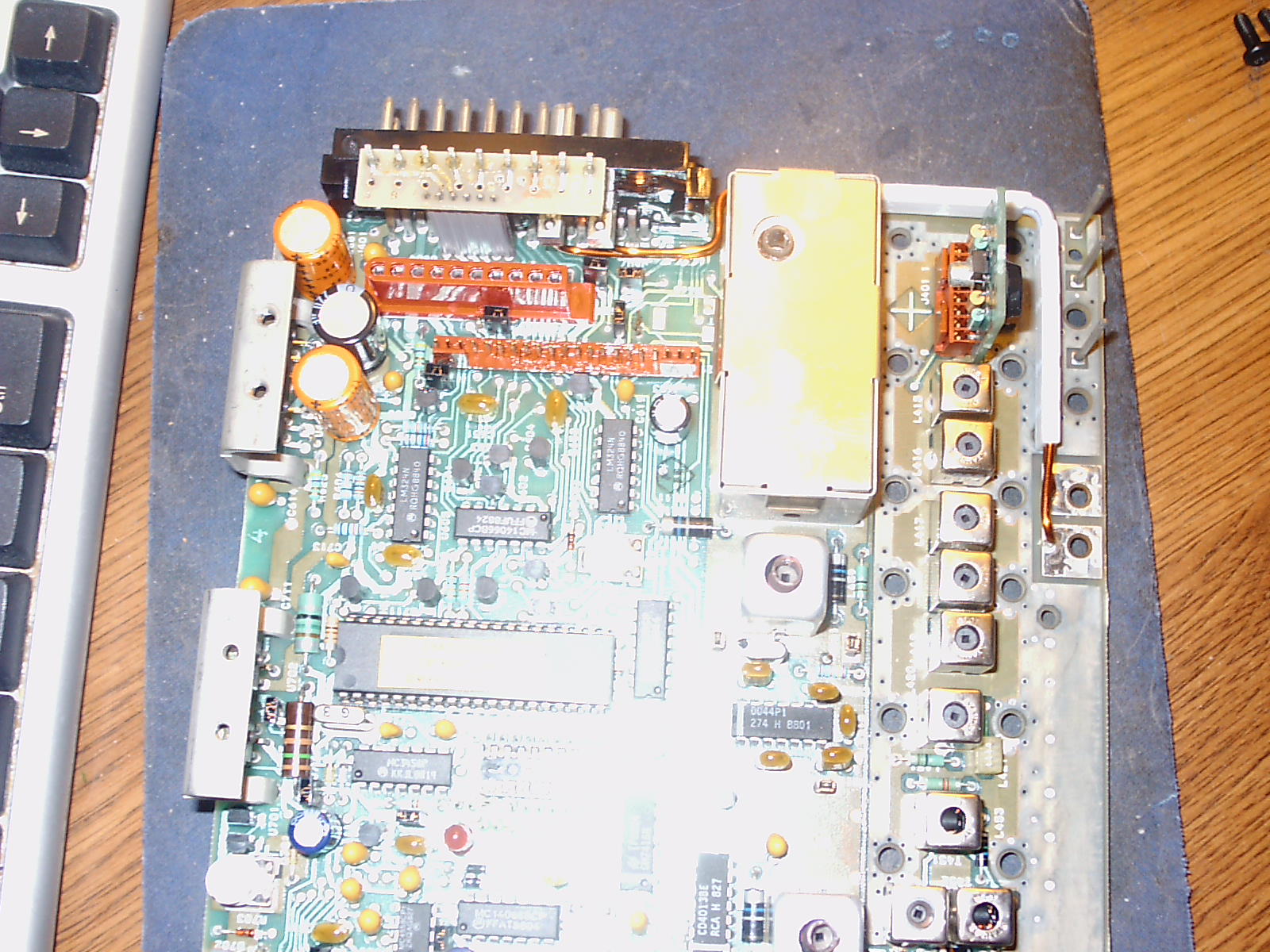
- Next, remove the bottom cover from the Delta if not already done.
- Referencing service manual, identify the screws attaching the control board to the chassis. They are located on the periphery of the board and one or two are in the center. There two (#8 size) star screws by J-601, and are 4 screws topside by the voltage regulator assembly. It is not necessary to remove the long rectangular shield covering the bandpass filters.
- With the screws all out, carefully pry up the board to see if it is free. If free, remove it from the chassis. You'll notice 3 long pins that will come out along with the board. Take care not to bend them nor misplace the white insulators from the chassis.
- Next, desolder the 2 enameled power leads from the Control Board.
- Clip the leads close to the 2 large pins (37 and 38) and remove both leads from the board.
- Carefully enlarge hole F (through the rubber and J-601 connector) so that the DB-25 cable can pass through it, but don't install the cable just yet.
- Remove the rubber gasket from J-601.
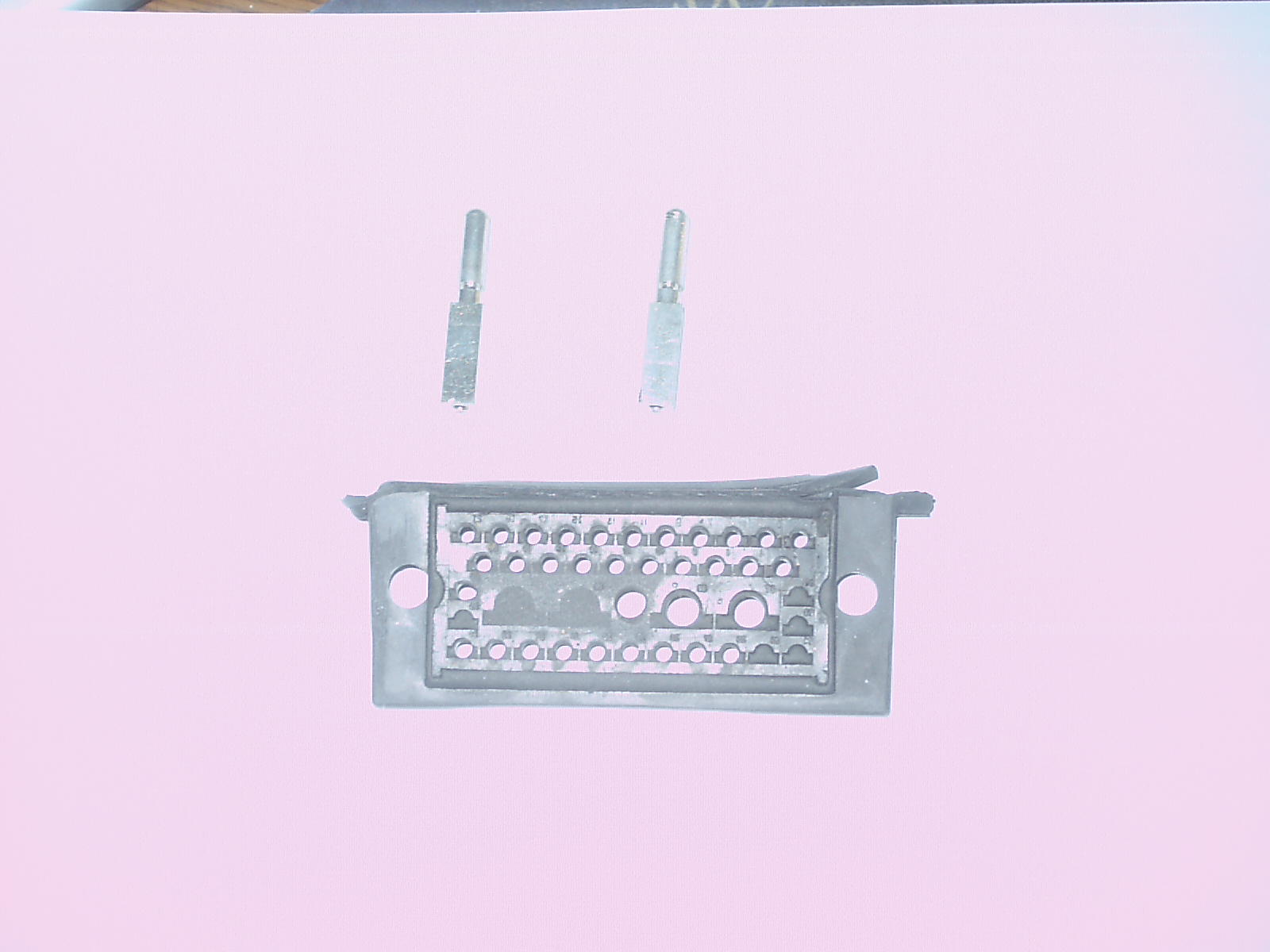
- Using a small screwdriver, remove the two 'C' clamps holding pins 37 and 38 to J-601. Discard both the pins and the clamps.
- Remove the Delta M/P and bend out the pins as it's much easier to remove the M/P with the control board out of the radio. It's also a good time to sever the 9 leads on A-601 (HL-1 to HL-9), if not already done.
- If you are using a relay, solder a 12 inch long piece of hookup wire to pin 19 'topside'. This lead will be later connected to the low current relay.
- Replace the rubber gasket.
- Carefully enlarge the holes from which the two enameled wires were removed. You'll be installing a red and a black #12 wire (stranded or solid) as the new power supply connections to the Delta. Take note of the stenciling on the chassis to see where the positive red (A+) and negative black (A-) leads connect. The negative lead is closest to the front of the chassis. It's important to get this right.
- 'Dress' around the Control Board in the same manner as the removed enameled wires were routed, with the red positive lead on top, routing them through the two holes made available by the removal of pins 37 and 38.
- Reinstall the Control Board taking care not to pinch or nick the heavy gauge wires. Make sure that the Control Board is properly seated before reinstalling the mounting screws.
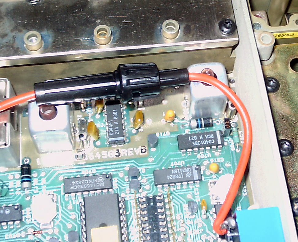
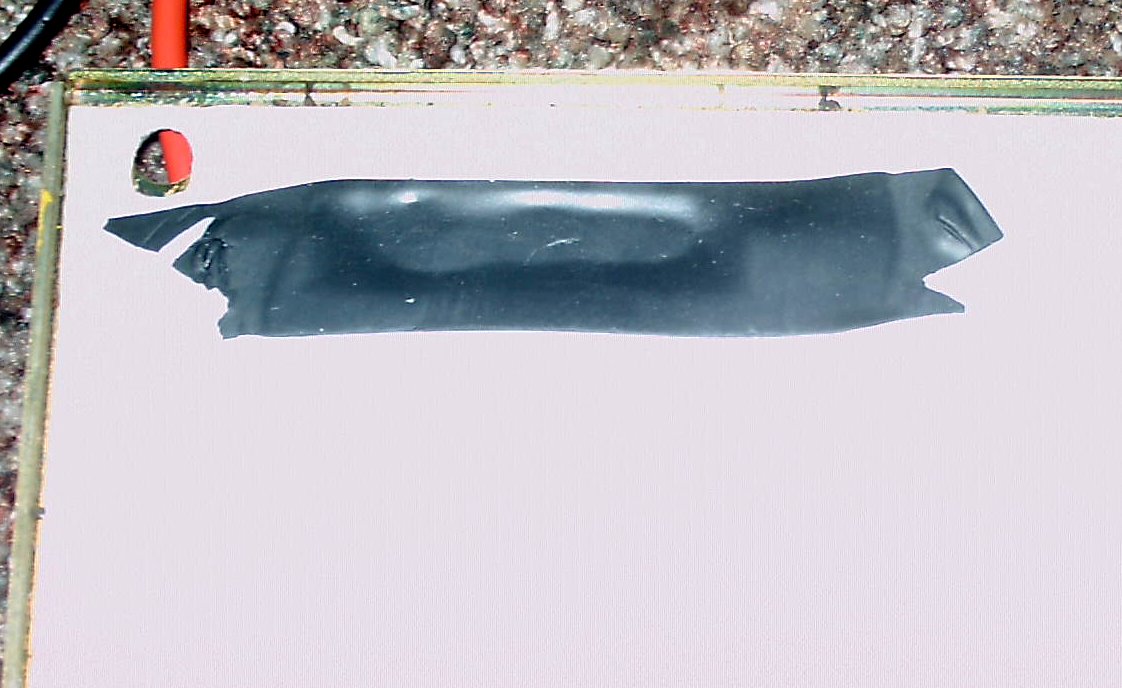
- Remove a small portion of the insulation on the red wire and solder one end of a fuse holder to it. This will be the power connection the relay which will switch on the power to the receiver and common circuits electronics. Tape the connection liberally, and position as shown.
- Apply hot glue to the power leads where they route through the connector so that are firmly affixed.
- Continue (below)
- Cut the male end off the cable, leaving the female DB-25 connector (shown above) on the other end (for the Control Head).
- Verify that you are connecting to the right pin by using a magnifying glass, if necessary.
- Remove about 10 inches of insulation (and foil shielding) from this end. Do not nick the insulation on any of the fine wires or the ground connection.
- Run the multi-conductor wire through the hole, securing the portion with the insulation with one or two cable ties.
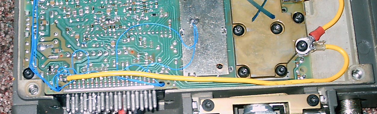
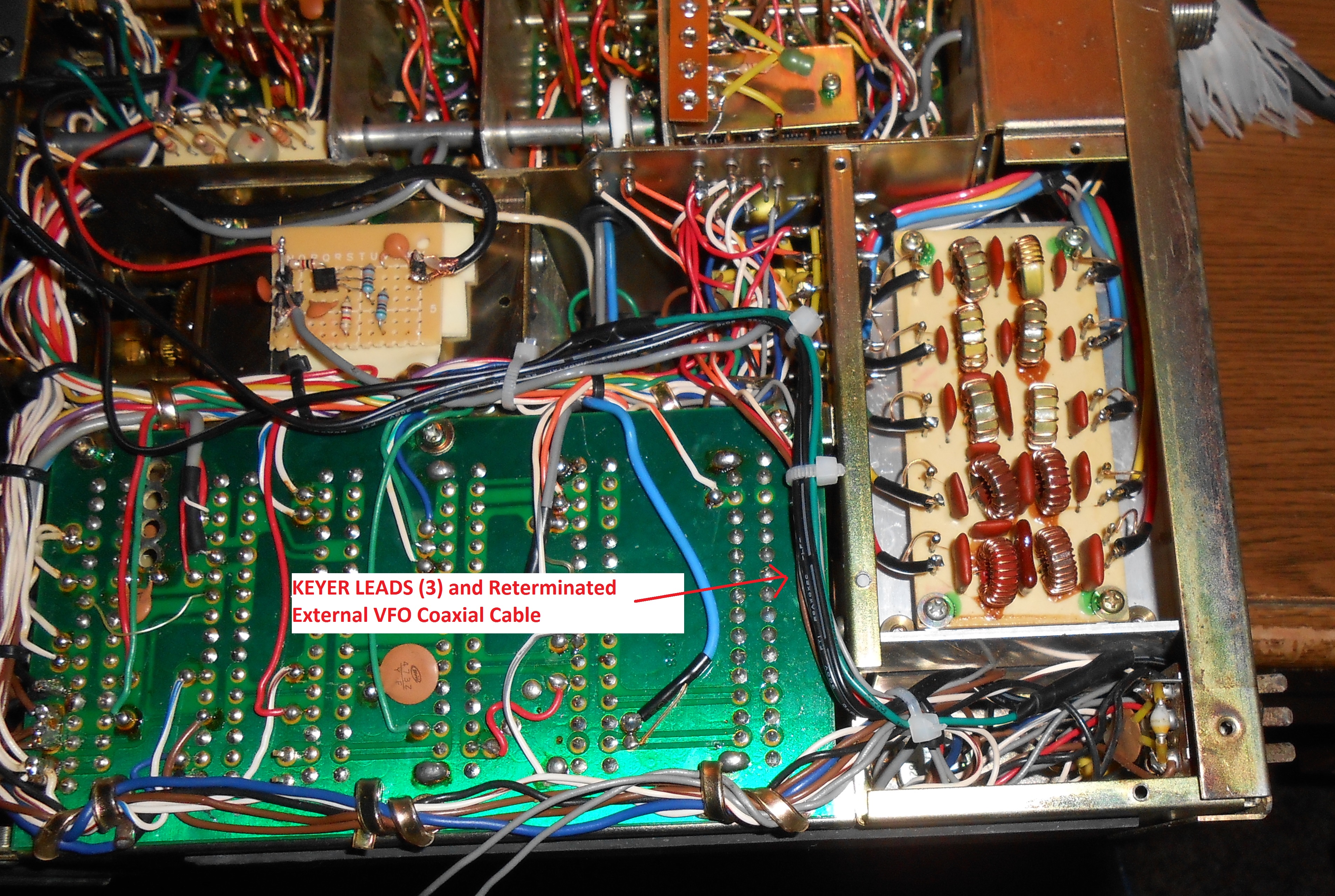
- Ten (10) of the DB-25 leads may be terminated on the HL-1 to HL-9 pins previously spared up. For the DB-25 conversion, there's no special assignment. In my conversion, I connected the Enable, Data, Clock, Channel Change, Transmit (PTT), COR(CAS), Volume / Squelch High, and the 2 speaker leads to A-601. Connect the Volume / Squelch High and CTCSS RCV leads together. If needed, ferrite beads, are placed on the leads, knotting them so that the beads would not interfere with the wiring on the pins.
- Five (5) leads (7, 12, 16, 21, and 22) and the shield wire are connected to the chassis ground, providing a robust ground connection.
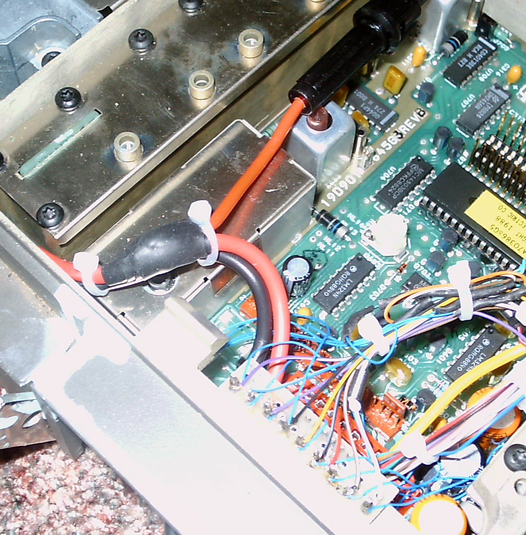
- On the bottom of the radio and connect the 9 leads on the HL-1 to HL-9 pins to their corresponding pins on either J601, or to the Delta M/P and to U-707, as shown here. Thus far, fifteen (15) of the DB-25 leads and the shield have been connected.
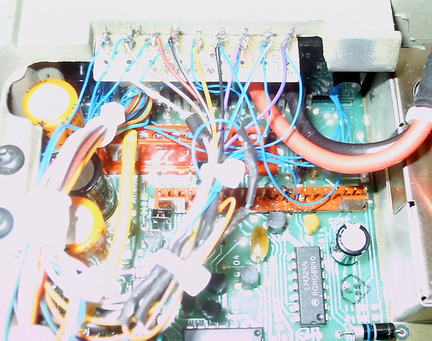
- Next, using heat shrink tubing and 30 gauge wiring, connect the Mike High, Volume Center, and Squelch Center to their coresoinding points on J601. This makes 18 of the 25 leads.
- If you plan to use the MX-COM's Transmit Audio Filtering, connect the TMT AUD IN and TMT AUD OUT leads to J-607, pins 1 and 2, respectively. Both leads require 2 ferrite beads. This makes 20 leads connected.
- Connect the CTCSS OUT lead using 2 ferrite beads.
- Connect the TMT OVER and LOCK leads to their corresponding DB-25 cable connections, with 2 ferrite beads on each. There are 2 remaining leads.
- Connect the 13 Volt lead to the Control Head to the output side of the low current relay.
- Connect the last lead ON / OFF to the winding of the low current relay. It will be used to activate the relay from the control head.
- 'Dress' the leads neatly, clamping where needed. Suspend the wiring above the control board so that the ferrite beads won't touch the board.
- Use hot glue to secure the DB-25 cable.
- Once done, replace the bottom cover and move on to final testing.
This approach will provide better maintenance and no drilled holes. (However, one needs to find a cable on eBay or from a dealer. The Connector Repair Kit - 19D900447G8, and a Thumbscrew - 19A705055P1 have since been discontinued).
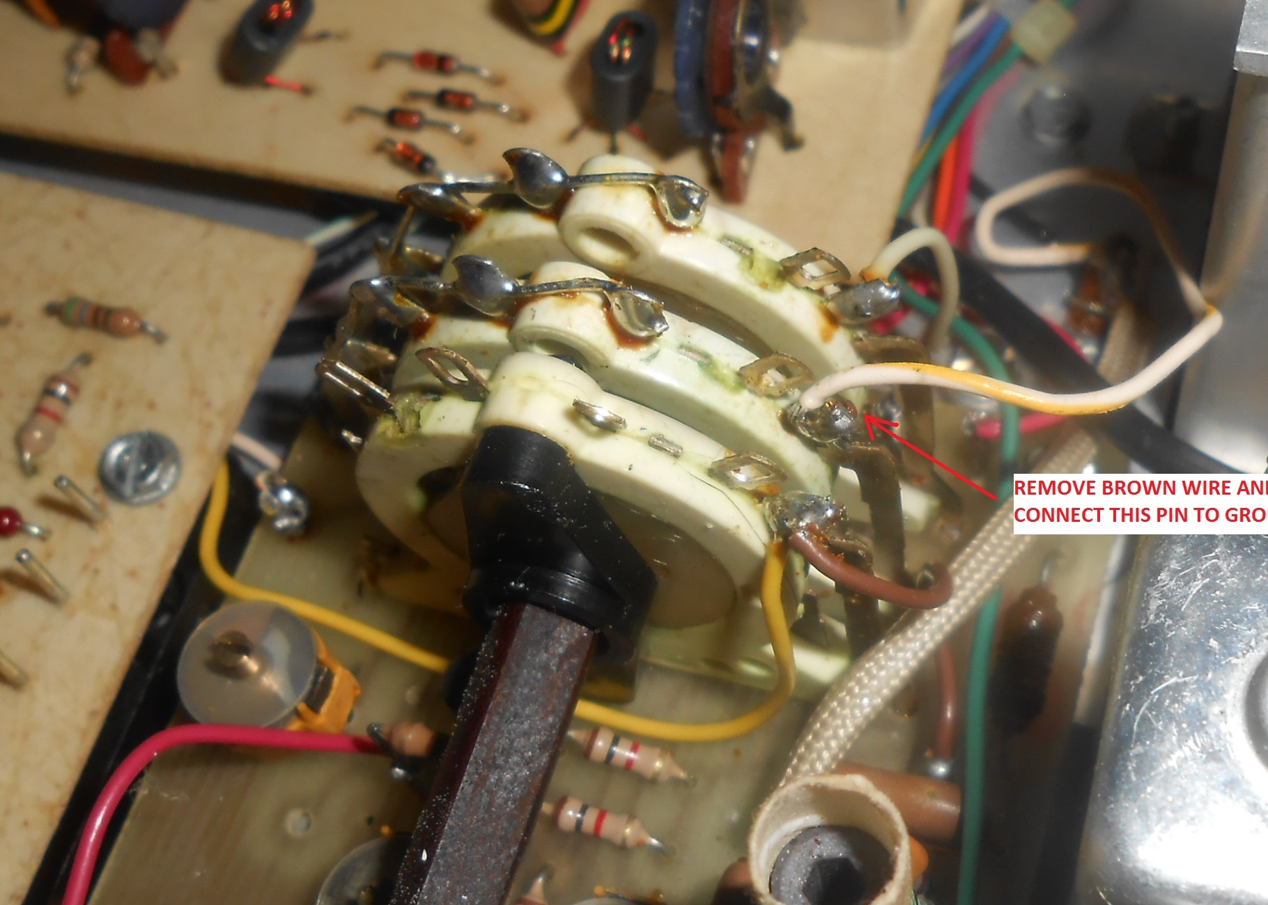
Open up P-601 and note the pins with wires on them. Most of these (as well as the wiring within the Delta) will be reused. These pins are so marked here. You'll need to move the pins that are not being used to the other locations requiring them and / or have a supply of spare pins from another source.
Since J-601 pins 5, 6 and 14 are grounded within the Delta, they make logical ground connections. Accordingly, connect five (5) DB-25 pins 7, 12, 16, 21, and 22 and the shield wire from the cable together with P601 pins 5, 6 and 14. Cover with heat shrink tubing - the grounding is done.
Referencing this Table, connect the eight (8) DB-25 wires within P601 to the remaining leads connecting to unmodified portions of the Delta, viz:
- Volume / Squelch High
- Volume Center
- Squelch Center
- COR (CAS)
- PTT (Transmit) - requires 2 ferrite beads
- Mike High - requires 2 ferrite beads
- Speaker (2 leads)
- 13 VDC - requires 2 ferrite beads
- ON / OFF
- TMT AUD IN - requires 2 ferrite beads
- TMT AUD OUT - requires 2 ferrite beads
- LOCK - requires 2 ferrite beads
- TMT OVER - requires 2 ferrite beads
- SPI - Data - requires 2 ferrite beads
- SPI - Clock - requires 2 ferrite beads
- SPI - Enable - requires 2 ferrite beads
- Channel Change - requires 2 ferrite beads
- CTCSS OUT - requires 2 ferrite beads
- CTCSS Receive
Ensure that all connections are correct. A test table provides resistance and voltage measurements at each of the DB-25 connector pins.
Make the resistance tests from the chassis to each of the pins in the DB-25 connector. They should all be close. Correct, as needed.
Next, apply power to the Delta by either:
- (low current relay) grounding the low current power relay contact DB-25 pin 17, or by
- (direct low power feed) applying 12 VDC to the lead running to pin 19 of J-601.
You'll have to build up a control head, and the required components are available. A large Radio Shack plastic enclosure works perfectly as it can house the P/C board, the keypad, LCD, the volume control (with an OFF / ON switch), a mike jack and even a small speaker.
A 'connectorized' control head may be used with several radios of the same or different frequency if the pin assignment convention is the same for each. Since the new M/P uses flash memory, it's easy to change the radio interface. See suggestions on Control Head construction.
Note: You may program channels used in any of these radios into their respective 'banks'. There are 5 banks of 20 channels each.
With the power off, connect the Control Head to the DB-25 cable. If you have the time, double check the end to end connections with your meter. If not, at least verify that the 13 VDC leads are wired properly.
Remove the fuse that connects the heavy red wire to the low current relay. Connect your 13 volt power supply positive lead to the relay feeder connection and the ground to the chassis. This lets you verify the receive and transmit synthesizers (one for each) without turning on the final amplifiers. Your shack's 13 VDC supply probably won't have enough power for the transmitter.
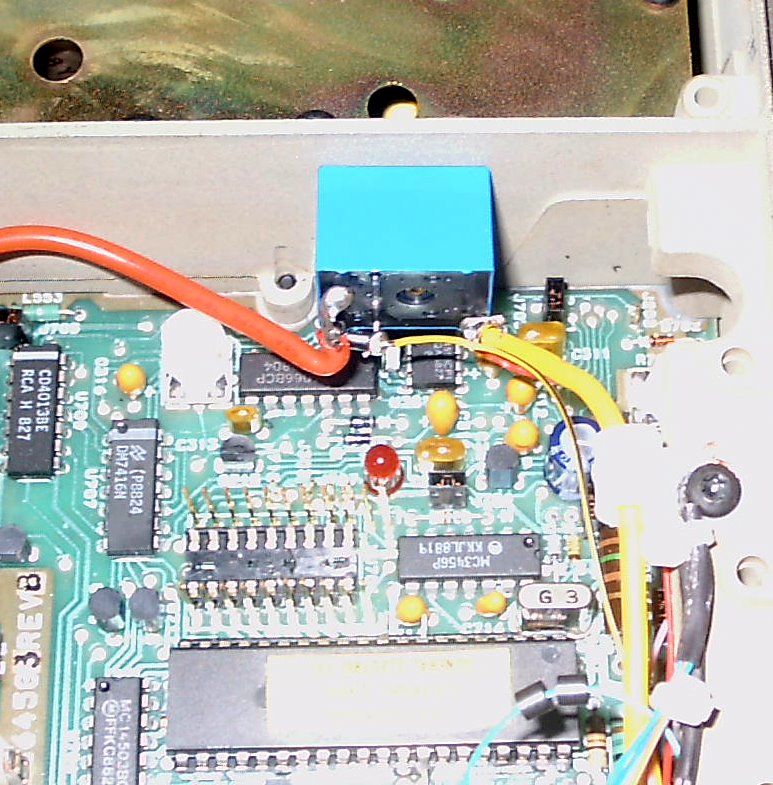
Temporarily connect a 30 gauge wire to J-702 - the VCO test point in the corner of the Delta's Control Board.
Switch on your power supply and turn on the Control Head OFF / ON switch. The LCD will display a frequency.
The Red LOCK LED on the Delta's control board will probably be lighted indicating a PLL out-of-lock condition.
Referring to the Command Manual, scroll down to find your radio's name and then activate it. The external M/P will save this setting in flash memory. The Delta's PLL may or may not lock.
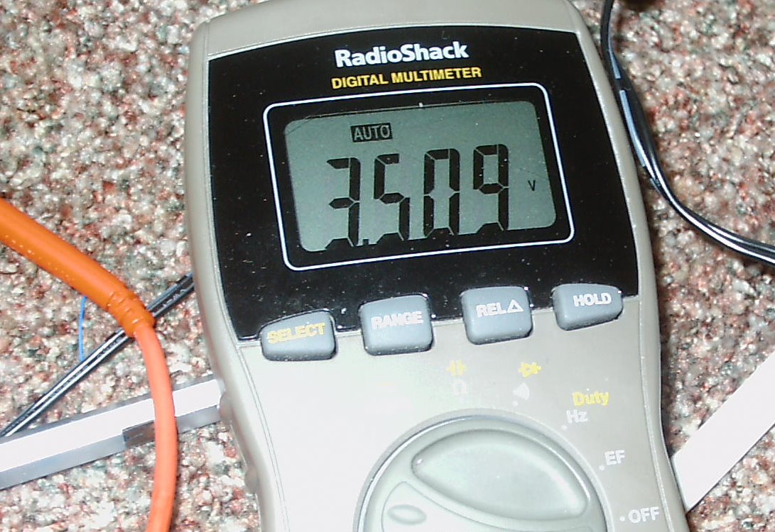
Set the frequency to 144.000 Mhz. The RED Lock LED might extinguish. Using a non-metallic screwdriver, adjust the Receive VCO (C220) clockwise for about 3.5 volts on your meter. This sets the low end of the VCO within the recommended range (3.5 - 7.5 volts) for reliable receive operation. The external M/P will select the frequency segment based upon the frequency entered. In my conversion, the Wideband Delta would receives up to168 Mhz, so I can listen to public service broadcasts and the weather channels.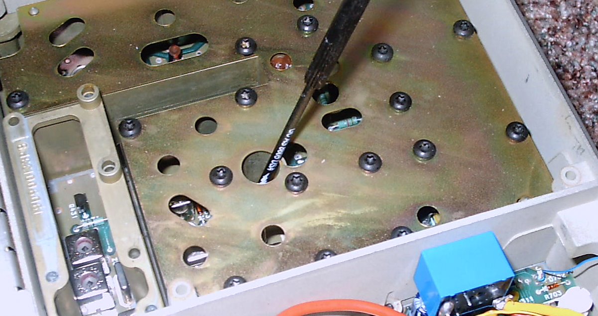
Reset the frequency to 144.000 Mhz. The Transmit VCO will be adjusted next. Depress the mike PTT switch to key the transmitter. Your VCO might lock, but the PLL voltage level will probably be too low (mine was 2.37 volts before the adjustment and was just barely locking). Using the proper alignment tool (I had to make one), turn the slug in L209 clockwise until the meter reads 3.5 volts, or as close as you can get before the slug 'bottoms out'. Although I didn't have to do it, some transmit VCO's might require some additional 'padding' around L209 - 5 or 10 pf should be adequate.
Before replacing the fuse, key the transmitter and note the time until the loop goes out of lock (i.e, stops transmitting). This checks the software timer (CCT) programmed into the eeprom. CCT values are, no transmitting limitation, 1/2 minute, 1 minute, etc in 30 second increments up to 3 minutes. If your radio transmits and you are satisfied with the CCT value that the previous owner programmed into the chip, you're all set.
If, however, you need additional transmit time, then the eeprom will need to be reporgrammed.
Once the Transmit VCO has been adjusted, replace the 5 amp fuse and continue to the operational tests.
Delta VHF Wideband - Low Split - 2 Meter Operation
Aside from the setting of the reference oscillator (later), these VCO's should need no adjustments as they already cover the 2 meter amateur band.
The external M/P will select the proper VCO segments based upon the frequency in use.
Delta VHF Narrowband - 2 Meters
Ensure that the transmit and receive VCO's are optioned for the proper frequency segment. Check the service manual for additional information.
You'll also have to realign the Receive Oscillator Injection and Front End Helical Filters. The filters are very sharp and probably set elsewhere, so they'll need readjustment. There's no intermod with this radio!
Delta VHF Narrowband - 6 Meters
Ensure that you have the proper radio as the Delta Low Band radios are built in 3 ranges, 29.7 - 36 Mhz, 23 - 42 Mhz, and 42 - 50 Mhz. Only the 42 - 50 Mhz radio will be suitable for a 6 meter conversion. The VCO's will need to be tuned to the proper frequency, and - according to the service manual - have about a 3 Mhz maximum range. This should be satisfactory for 6 meters as most FM activity is between 52 - 54 Mhz.
The front end alignment of the radio may also have to be 'tweaked'. Check the Service Manual for additional information.
Delta VHF Narrowband - 10 Meters
Check that you have the proper radio as the Delta Low Band radios are built in 3 ranges, 29.7 - 36 Mhz, 23 - 42 Mhz, and 42 - 50 Mhz. Only the 29.7 - 36 Mhz radio will be suitable for a 10 meter conversion. The VCO's will need to be tuned to the proper frequency, and - according to the service manual - have about a 3 Mhz maximum range. This should be more than adequate for 10 meters. Check the Service Manual for additional information.
I have not converted a Delta for 10 Meters, but the interface connections to the Delta's M/P are identical to the other conversions and should work. The M/P has been coded for a 10 meter conversion.
Delta UHF Wideband - 440 Mhz
More information to follow....
- Connect ground and the +12 to 13.8 VDC leads to the PA using at least #10 stranded wire and the appropriate fuse.
Crucial Note - Place the fuse as close to the car battery as possible. This way, a ground on the power cable running elsewhere in the car (say, under the carpet or near the gas tank) will not burn up your car, or cause even more severe consequences! For Delta's running close to 100 watts, use a 25 to 30 amp fuse. For Delta's set to 45 to 60 watts, use a 15 to 20 amp unit. Don't omit the fuse!
- Key the transmitter with a either a dummy load or an antenna connected. Verify the presence of RF with an SWR bridge, if possible. Key the transmitter repetitively to verify that RF is always present each time you key up.
- If the RF output is intermittent or missing, measure the voltage on pin 32 of the Delta's internal M/P as you push the PTT button. If the voltage remains at 2.7 volts (or thereabouts) and if the transmit synthesizer is locked (red light off), then there is a timing issue between the external M/P and the Delta proper - - as the Delta's M/P is not issuing the transmit signal. This might be caused by interactions within your Delta and / or variances in the components (e.g. R14 or C10) in the control head. Some Deltas work properly while others do not.
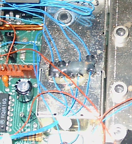
- To remedy this interaction, circuitry has been provided on the board to FORCE the Delta into the transmit mode when the PTT has been depressed and only when the Transmit synthesizer is locked. Specifically, these components are R15, R16, Q7, Q8, JP10 and JP13.
- To activate this feature, jumper pins 1 and 2 of JP13. When the PTT is depressed, the external M/P will key the radio and then activate the WRMI (We Really Mean It) signal 25 ms. thereafter, giving the Delta's antenna change over relay time to operate before the transmitter is actually turned on.
- If the synthesizer is unlocked, the positive voltage on the Delta's LOCK lead will disable the WRMI lead so that Q8 cannot switch on and ground the transmit override lead. When the PTT switch is released, the transmitter RF will be turned off before the antenna changeover relay is released.
- Connect either a dummy load or an antenna, set the frequency within the amateur band and make a transmission or two. You should not have to re-adjust the Delta's deviation control.
- Try out all of the M/P commands.
Turn on the radio and select a CTCSS tone frequency.
If you have another radio (like a hand held) with
CTCSS
capability, transmit with the same CTCSS tone selected and verify that
the Tone Detected LED
lights. Transmit with the Delta and set the tone level on the
CTCSS board
so that the tone
activates tour hand
held's receiver (when set to break the squelch when the correct CTCSS
tone is received).
n) Hitting the Road
Mount the unit in the trunk of your car (or place it somewhere in your shack), ground the chassis to the car frame, mount your control head in a convenient spot, connect the high power leads to your car battery (again, don't forget the fuse), and you're all set to 'rock and roll'.
Note: Even though this conversion will not affect the Delta's 'spectral purity', the FCC's 'type acceptance' was voided when the radio was modified to accept the frequency agile controller. Therefore, it can never legally be used to transmit on non-amateur frequencies.
|
Function |
Delta Connection Points & Connector Pins |
Ferrite Beads |
J-601 Pin Used
|
For Modified Plug Delta Changes? |
DB-25 Cable Pins |
M/P Board Pins |
Function / Comments |
| 13.2 VDC | P-601 Connector (see powering considerations) |
- | 26 | Clip HL-1 (see text) | 3 | None |
Switched DC to M/P |
| Ground | P-601 Connector | - | 5 | None | see text | MAIN Pin 9 |
Ground |
| On / Off | P-601 Connector (see powering considerations) |
- | 27 | Clip HL-2 (see text) | 17 | N/A |
Low Power Relay |
| SPI - Enab | A-701 (M/P) - Pin 8 | 2 | 31 | Clip HL-6 (see text) | 15 | PLL - Pin 1 | PLL Enable |
| SPI - Clock | A-701 (M/P) - Pin 10 | 2 | 29 | Clip HL-4 (see text) | 13 | PLL - Pin 2 | PLL Clock |
| SPI - Data | U - 707 (Inverter) - Pin 5 | 2 | 30 | Clip HL-5 (see text) | 10 | PLL - Pin 3 | PLL Data |
| Chan Chg | A-701 (M/P) - Pin 33 | 2 | 28 | Clip HL-3 (see text) | 14 | Main Pin 6 | PLL / Wideband |
| Transmit | P-601 Connector Pin 11 | 2 | 11 | Reuse Pin 11 | 1 | PLL - Pin 4 |
DELTA PTT |
| COR Detect | P-601 Connector - Pin 12 | - | 12 | Reuse Pin 12 | 5 | MAIN - Pin 1 | 5.1 volt zener |
| Mike High | P-601 Connector - Pin 9 | 2 | 9 | Reuse Pin 9 | 9 | N/A |
- |
| Speaker | P-601 Connector - Pin 18 | - | 18 | Reuse Pin 18 | 19 | N/A | NO Ground! |
| Speaker | P-601 Connector - Pin 20 | - | 20 | Reuse Pin 20 | 20 | N/A | NO Ground! |
| Vol / Squ High | P-601 Connector - Pin 7 | - | 7 | Reuse Pin 7 | 25 | N/A |
- |
| Vol / Squ Low | P-601 Connector - Pin 6 | - | 6 | Reuse Pin 6 | see text | N/A |
- |
| Vol - Center | P-601 Connector - Pin 8 | - | 8 | Reuse Pin 8 | 4 | N/A |
10K to 25K |
| Squ - Center | P-601 Connector - Pin 15 | - | 15 | Reuse Pin 15 | 8 | N/A |
10K to 25K |
| CTCSS OUT | Connect to Delta J603 - Pin 15 | 2 | 33 | Clip HL-8 (see text) | 18 | Tones Pin 1 | Transmit CTCSS |
| CTCSS RCV | P-601 Connector - Pin 7 | - | 7 | Reuse Pin 7 | 2 | Tones Pin 2 | Receive CTCSS |
| TMT AUD OUT | Delta P-607 - Pin 2 | 2 | 34 | Clip HL-9 (see text) | 23 | Tones Pin 4 | Proc
MikeOutput |
| TMT AUD IN | Delta P-607 - Pin 1 | 2 | 32 | Clip HL-7 (see text) | 24 | Tones Pin 5 | 'Raw' Mike Input |
| TMT OVER | A-701 (M/P) - Pin 32 (see text) | 2 | 2 | Sever FB-2 Lead on J-601 and Reuse Pin | 11 | JP10 - Pin 2 | Transmit Override |
| LOCK (PLL) | A-701 (M/P) - Pin 1 | 2 | 3 | Sever FB-3 Lead on J-601 and Reuse Pin | 6 | JP10 - Pin 1 | PLL Lock Ind. |
Test Table - DB-25 Cable Connections - for a Wideband Delta VHF High Split
Pin # Function R to Gnd Volts Comments 1 Delta PTT Inf 6.35 PTT Lead used to Key the Delta Radio 2 CTCSS RCV Inf 0 CTCSS from the Delta to the MX-465 Chip 3 M/P Board Power 1 M (Capacitor)
13 4 Volume Center Inf 4.85 Place P608 (or Strap J603 Pins 12 & 14) 5 COR (CAS) 10K 8.98 Ensure 5.1 Volt Zener Present on M/P Board 6 Lock Inf 3.25 Delta PLL Lock Indicator 7 Ground 0 0 Chassis Ground 8 Squelch Center Inf 0 Place P608 (or Strap J603 Pins 12 & 14) 9 Mike High 1.36K 8.99 Use a Delta / Rangr microphone 10 SPI Data 10.6K 4.85 Serial PLL Data Connection 11 TMT OVER Inf 2.49 Transmit Override (see text) 12 Ground 0 0 Chassis Ground 13 SPI Clock 10.62K 4.85 Serial PLL Clock Connection 14 Channel Change 10.64K 4.85 Enables Wideband / Fast PLL Lock 15 SPI Enable 10.69K 4.85 PLL Enable Connection 16 Ground 0 0 Chassis Ground 17 ON - OFF Switch Inf 13 Activates (Fused) Low Current Relay 18 CTCSS TMT Inf 4.46 CTCSS Lead from MX-465 to Radio 19 Speaker 40K (Capacitor) 6.60 Don't Ground 20 Speaker 40K (Capacitor) 6.84 Don't Ground 21 Ground 0 0 Chassis Ground 22 Ground 0 0 Chassis Ground 23 TX AUD OUT Transmit Audio Out 24 TX AUD IN Transmit Audio In 25 Vol / Squelch High Inf 0 - Shield 'Shields' Cable 1.6 Ohm 0 G.E.and the product names Phoenix, Delta, Rangr are trademarks of Ericsson General Electric Mobile Communications.
DISCLAIMER - - If you follow the steps outlined herein, you do so at your own risk. I cannot, nor will not, be responsible for any possible damage to radio equipment, personal property, to yourself or to others caused by modifications that you may make as a result of your reading this.
The M/P controls TRANSMITTING and receiving on many frequencies, suitable for a wide range of HF, VHF and UHF needs. In the USA, TRANSMIT operation requires a license issued by the FCC for the class of operation intended. Amateur radio licensees must maintain strict control over their equipment, preventing unlicensed operation within or outside of the amateur bands.
Copyright 2010 - K3JLS