Host your Web site with iPage!
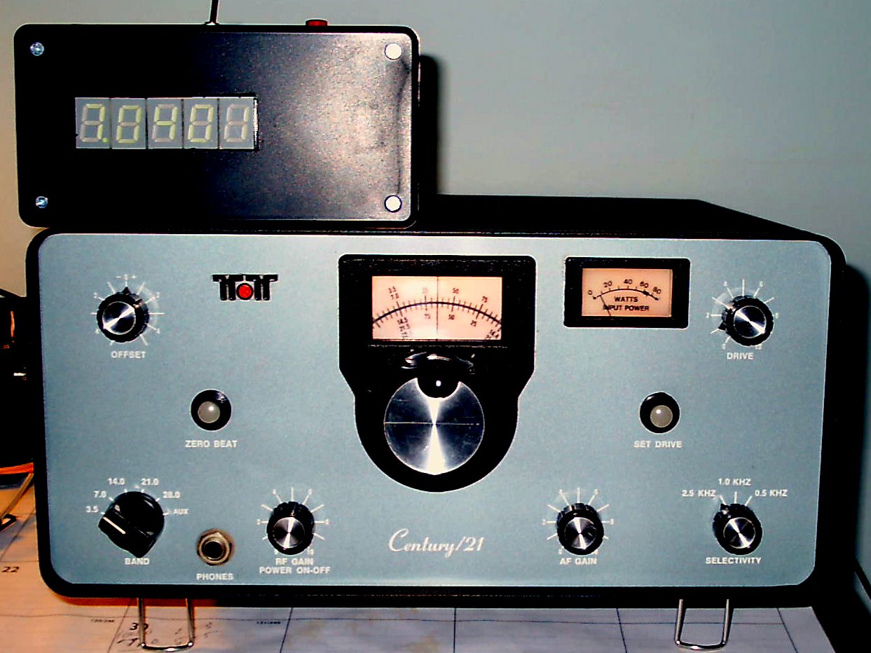
Digital Frequency Counter for the Ten-Tec
Century 21 Analog Transceiver
CAUTION
- To undertake this modification, you need to remove
the bottom cover of your Century 21 transceiver. When connected to the 120 volt AC
line, there is
always the possibility
of receiving a dangerous
and possibly life
threatening shock.
If you have never worked on 'live' equipment and / or if you
don't think you are able to complete the modification safely and
satisfactorily, please
do not attempt it.
I cannot and will not be responsible for any accidents occurring as a
result of your reading this web page.
1.
Introduction
The Century 21 CW only transceiver was first introduced in the late
1970's. Well received by Novices and experienced hams alike,
it resembles the 'EverReady
Bunny' in that it just goes, and goes and
goes.' The radio is equipped with a rugged internal power
supply and has a circuit breaker on the power ON / OFF switch to
protect the final amplifier transistors in the case of an SWR mismatch.
It works on the 80, 40, 20, 15 and 10 meter bands in the CW
portion. Aside from an infrequent rebuilding of the PTO, it's
a virtually trouble free, fun radio.
When introduced, the Ten-Tec engineers
offered two options. The first was a plug-in crystal
calibrator and the second was an optional keyer. Anyone who
has used the Century 21 will quickly
understand why the calibrator was
required. The frequency determining elements of
the Century
21 consist of a conventional 5 - 5.5 Mhz VFO (the PTO) beat against
heterodyne oscillator crystals. For example, the Century 21
uses the following heterodyne crystals:
- 80 meters (3.5 - 3.75 Mhz)
- 9.0 Mhz
- 40 meters - (7.0 - 7.25 Mhz)
- 12.5 Mhz
- 20 meters - (14.0 - 14.250)
- 9.0 Mhz
- 15 meters - (21.0 - 21.25 Mhz) - 16.0 Mhz
- 10 meters - (28.0 - 28.25 Mhz) - 23.0
Mhz
- 10 meters - (29.0 - 29.25 Mhz) - 23.5
Mhz
When the bandswitch is in the 80 meter
position, the circuitry within the Century 21 beats the PTO against the
9.0 Mhz crystal to produce a signal in the 3.5 Mhz range. In
other words, the PTO frequency is subtracted from the 9.0 Mhz crystal.
Conversely, in the 20 meter position, the 9.0 Mhz frequency
is added to the PTO to produce a 14 Mhz signal.
For 40 meters, the PTO
is subtracted from the 12.5 Mhz crystal, while the PTO is added for the
15 and meter bands. The PTO's circular dial has been
calibrated accordingly. I would
assume that the Century 22's circuitry is similar.
2. Calibration
Issues
For operation well
within a frequency band segment, the
Century 21's analog frequency display is adequate.
However, to
work near the band edges (e.g. to catch that
elusive DX on 40 meters) or to be exactly on the recognized QRP
frequencies, some form of
frequency calibration is required. While the dial displays the
frequency in 5 Khz increments, and while the PTO design is very well
done, the PTO is not linear throughout its range.
When coupled with the fact that the
heterodyne oscillator
crystals are not equipped with trimmer capacitors, it's well possible
to end up with a plus or minus 5 Khz (or more) deviation at any one
frequency,
even if the radio has been precisely adjusted for one band of
operation.
3. Adding a
Digital Frequency Counter
A quick search of the web will show the work done by N5ESE
in adapting the Don Hendricks kit
as a digital
display for the Century 21 transceiver.
At first, I had considered implementing this solution, but
was reluctant to cut the faceplate of my mint Century
21. So, I searching the web, I came across a nifty 5 digit
counter circuit developed by Wolfgang Buscher DL4YHF.
'Wolf' has taken ample time to describe this very clever
project
and even includes copies of the source code for anyone who is
interested in 'rolling their own' from scratch. Even better
yet,
Sunil Lakhani - VU3SUA has developed a 5 digit frequency counter kit
based upon DL4YHF's design.
The remainder of this website describes my experiences for anyone who
would like to either replicate or build upon them. Of course, the
counter can be mounted within the Century 21 if you are willing to cut the nice front panel.
4. DL4YHF Counter Design
I found this design preferable for this conversion because the
counter's microprocessor can store in its eeprom both the precise
frequency of the heterodyne oscillator crystal and whether the PTO
frequency should be added to or subtracted.
This way, there's no need for any interpolation tables or any
other steps once the counter has been set up for a particular band. Just a flick of a switch and a
few button presses accomplishes the programming.
Better yet, the counter will power up already programmed
if the Century 21 is set to the same band.
5. Modifying the Century 21
Transceiver - Unplug the Radio and
Remove the Bottom
Cover
I decided to see what existing jacks
could
be used. On the rear panel are three (3)
RCA jacks
(if you want to call them that). Two of these supply 12 VDC
and
ground, while the third is used for the CW key. Three (3)
jacks
are needed to remote the digital display.
If
you'll note, there is a hole with a plastic plug in the rear of the
cabinet just below the SO-239 RF connector. I guess we should
be
thankful that Ten-Tec did not decide to use another RCA type jack for
the antenna connection (like
Heathkit did on some of their SB / HW series radios).
If this plastic plug is removed (and saved for possible later
use), an ordinary 1/4 inch jack will fit nicely in the
hole. Wired back to the keying lead removed from the
KEY RCA connector, this now becomes the key jack
and frees up one of the 3 RCA jacks.
Two of the RCA jacks have 12 VDC on them. By cutting the
jumper
between two of them, another jack is spared up. And that's it!
The remaining functional RCA jack will provide the 12VDC to
the
display while the other two will provide the frequency signal (over
coax) and the third will provide a conduit over which the heterodyne
oscillator 'sampler' relay will be operated.
6. Adding the Interface
Board - Schematic Information
The
logic in the digital display needs to be able to count both the
heterodyne oscillator and the VFO (PTO) to compute the actual
frequency. To accomplish this, an interface circuit was built
within the Century 21 radio. The interface circuitry consists
of
a small, Radio Shack SPDT relay to switch between the heterodyne
oscillator and the PTO (VFO) and a high impedance FET 'source follower'
that both isolates and buffers the signals. Without
the FET source follower, the coax from the external counter will pick
up all sorts of RF signals and really mess up the receiver.
A SPST switch mounted on the display itself - when operated -
will switch the signal from the heterodyne oscillator to the external
display. The push button on the display is then used to step
through the menu options to either ADD
or SUB tract
the PTO signals from the heterodyne oscillator value. After
this
selection is made, the switch is released, the interface board relay is
released, and the PTO signal is sent to the display where the software
logic displays the actual operating frequency. It works quite well.
Before
wiring up the interface board, cut a small piece of either perf board
or P/C board and verify that it will fit on the rear corner of the
heterodyne oscillator board, close to the existing coaxial connection.
The rear screw holding the Ten-Tec board to the chassis will
be
used to mount the interface board.
Wire up
the board and carefully test it out before mounting it. If
using
the small Radio Shack relay, you may want to install a 100 ohm resistor
(R15) in series with its operate path to limit the current flowing
through the relay winding. I had the first relay I used short
out
for some reason, even though the measured current was almost exactly
what Radio Shack had specified.
Also,
don't forget to add the transient suppressing diode (D7) around the
relay winding as the transients generated when the relay is released
might feed back on the 12 volt power lead and damage the electronics
within the Century 21.
On the bottom of the radio, place
isolating .01 mf capacitors C8 and C9 right at the outputs of the PTO
and heterodyne oscillators. Mount the interface board
and run miniature coax to the respective connection points on the
board. The
mounting screw also provides an electrical ground.
Next, run a third piece of miniature coax to one of the 2 spare RCA
jacks on the rear of the board. This is the lead that will
carry
the PTO / heterodyne oscillator signal to the display over another
length of coaxial cable. Label
it DISPLAY.
Connect an internal source of 12 VDC power to the interface board and
provide a connection to operate the relay over the last spare RCA
socket on the rear of the radio. Label this connection RELAY. The undisturbed RCA connection
can be labeled POWER.
Power up the radio and verify that it
still works properly. Carefully
ground the heterodyne oscillator relay lead and verify that the relay
operates and that the radio is still working properly.
If you have a frequency counter, connect
it to the DISPLAY.
The counter should display the PTO (VFO) frequency.
Move
the Century 21's tuning knob and verify that the counter changes
accordingly. Ground the RELAY
connection and verify that your counter now displays the heterodyne
oscillator frequency. Change the bandswitch position and verify that
the counter follows.
When done, remove the AC power (unplug the
radio), disconnect your counter, unground the RELAY
connection, and replace the bottom cover. You are now ready
to build, connect and calibrate the display.
7. Building the Counter
The counter comes with good instructions and is easy to build.
As it didn't come with a schematic drawing, I traced it out
and
provided a schematic.
Here are the changes that I made during the construction:
- Replace Q1 (near the PIC M/P) with a 2N3904 NPN transistor
(same mounting arrangement). The 2N3904 will enable the
counter to count the frequencies of the 15 and 10 meter heterodyne
oscillators. The
stock
transistor provided in the kit will not
count
these frequencies.
- Replace the 10K resistor associated with the same
transistor with a 33K base pull-up biasing resistor. This is also needed to measure
the higher frequencies.
- Forget about using the cables provided to connect the power
/ ground and the frequency in / ground leads. They didn't make good enough
contact (at least in my kit). Hard wire these
connections instead.
8. Making a Suitable Enclosure
One thing you can still find at Radio Shack is a good plastic
enclosure. I used the smallest I could find that would hold
the
electronics which is stock number 270-1805. The plastic in
these
boxes is easily cut
with an Exacto
(or similar) knife.
I mounted the electronics on the front panel of the box, as shown in
the attached picture. To make the board fit, I had to cut
down
one of the mounting 'pillars' and notch the side of the box.
When it's
all said and done, it fits rather nicely.
The switch to control the heterodyne oscillator relay and the push
button to manipulate the counter itself are mounted on the top of the
box. The 3 RCA jack connections for the power, signal and
relay
leads are mounted on the rear. These cables will connect to
the
Century 21.
9. Initial
Tests
Connect
the display to your Century 21 and turn the power on - both the Century
21 and your display should light up and some frequency should be
displayed. If the heterodyne oscillator switch is operated,
you
should see the frequency of the oscillator crystal depending upon the
position of the bandswitch, as shown previously.
This frequency will NOT change as the VFO knob is turned.
If the heterodyne oscillator switch is released, then the display will
show some frequency which WILL change as the VFO knob is turned.
If these two steps do not work properly, then recheck the construction
of the counter itself, the inferface circuit mounted in the Century 21
and / or the cabling between the two unuts.
10. Counter Calibration
The counter needs to be calibrated to
insure accurate freequency reporting. There
are two ways to calibrate it. Whichever you use, let
both
the Century 21 and the digital display warm up for at least 15 minutes:
- If
you have an accurate frequency counter, connect the output of
the PTO (VFO) to your frequency counter and note the frequency.
Then, remove your frequency counter and plug the coax from
the
Century 21 into the counter and note the frequency displayed, without
moving the Century 21's tuning control. Adjust the variable capacitor
in the digital display to the same value you noted on your counter and
you're all set. Verify your work by tuning CHU on 7335.0.
- If
you don't have a reliable frequency counter, but if you can receive CHU
on 7335, you can follow this iterative adjustment procedure.
Connect the digital display to Century 21 and tune the radio
until you can receive CHU on 7335 or thereabouts on the analog dial.
Tune
in CHU until you have an exact zero beat. Following the procedure shown
below, set up the display to receive on the 40 meter band.
Without moving the dial, take note of the reading on the
digital
display. If you can, try to adjust the variable capacitor in
the
digital display to make the counter read 7335.0, or as close to this as
you can. Then readjust the display for the 40 meter band
which
lets the display measure and sample the heterodyne oscillator
frequency. When you release the the heterodyne oscillator
switch,
take note of the display. If it reads 7335.0, then everything
is
adjusted properly. If not, then you'll have to repeat the
procedure until the 'zero beat'ed' CHU station displays as 7335.0.
11. Using the Digital Display
Using the digital display is very easy:
- First, select the band of interest on the Century 21,
- Operate the heterodyne oscillator switch on the remote
display,
- Depending
upon the band, either add or subtract the VFO frequency by stepping
down (remote display push button) through the menu items:
- For 80 and 40 meters - SUB tract
- For all other bands -
ADD.
- Hold the display push button down until either SUB or ADD blinks,
- Release the display button (and the display will show all
zeroes),
- Release the heterodyne oscillator switch and the actual
frequency will be displayed.
- That's it!
When
the radio / counter is powered
off, the offset
information will be retained
in the display processor (PIC)'s
eeprom memory.
So, if you are going to operate on the same band the next
time,
you're all set. Just turn the Century 21 on and get to it!
Note - changing the offset control while
in the receive mode
will make corresponding changes
to the digital
display - neat-o!
12. Possible 6 Digit Counter Design
Depending upon demand and subsequent interest, I may make availabe a
true 6 digit version of this counter by designing a new P/C board and
modifying the DL4YHF code to make band changing easier (no need to step
down through the menu for adding or subtracting). The PIC can
easily be reprogrammed. Please email
me if you are interested.
13. Ordering the Counter Kit from
Sunil Lakhani - VU3SUA
You can reach Sunil at the following
address:
http://bitx20.com/
You might also check to se if he has any frequency counter kits
available on eBay. I bought mine for $22, and that included
free
shipping. That's a really tough deal to beat.
14. Modifying the Century 22
At first blush, the Century 22 would appear to have the same frequency
conversion scheme as the Century 21. If so, then there's no
reason why this counter could not be used in conjunction with the
Century 22. Perhaps someone out there would be willing to try
it out???
15. Conclusion
Our thanks to Wolfgang - DL4YHF - for his ingenious design and
willingness to share it with his fellow amateurs. His example
personifies the spirit of our hobby. Also thanks to Sunil
Lakhani
- VU3SUA - who is marketing this counter as an inexpensive kit.
I'm sure that Wolfgang would be
interested in hearing about your conversions!
73's - Joe - K3JLS
DISCLAIMER
- - If you follow the
steps outlined herein, you do so at your own risk.
I cannot, nor will not, be responsible for any possible damage to radio
equipment, personal property, to yourself or to others caused by
modifications that you may make to the radio as a result of your
reading this.