Equipping the
Ten-Tec Digital Century 21 with a Dual Digital - DDS VFO
CAUTION
- To undertake this modification, you need to remove the
covers of your Century 21 transceiver. When connected to the 120 volt AC
line, there is
always the possibility
of receiving a dangerous
and possibly life
threatening shock.
If you have never worked on 'live' equipment and / or if you
don't think you are able to complete the modification safely and
satisfactorily, please
do not attempt it.
I cannot and will not be responsible for any accidents occurring as a
result of your reading this web page.
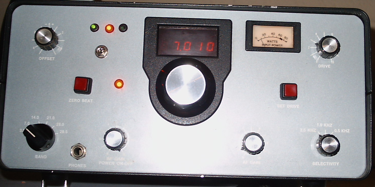
1. Introduction
The Century 21 CW only transceiver was first introduced in the late
1970's. Well received by Novices and experienced hams alike,
it
resembles the 'Ever
Ready Bunny' in
that it just goes, and goes and goes.' The radio is equipped
with a rugged internal power supply and has a circuit breaker on the
power ON / OFF switch to protect the final amplifier transistors in the
case of an SWR mismatch. It works on the 80, 40, 20, 15 and
10
meter bands in the CW portion. Aside from periodic rebuilding of the PTO,
it's a virtually trouble free, fun radio.
This website shows how to upgrade your Digital Century 21 with an
extremely stable, backlash and warble / manitenance free, Dual Digital VFO.
Once done, your Century 21 will work in
the SPLIT frequency mode without any external VFO. Best
of all,
you'll never have to rebuild that vexatious PTO.
The converstion consists of removing the existing PTO
and installing a suitable mounting to hold the optical encoder
of
your choice. (Depending
upon the length of your optical encoder's shaft, you may have to either use a 1/4 inch extender or cut
the sheet metal of the sub panel). Holes are drilled in the chassis to support a mounting 'platform' for the DDS VFO. The DDS VFO circuit board is then
connected to various points within the radio.
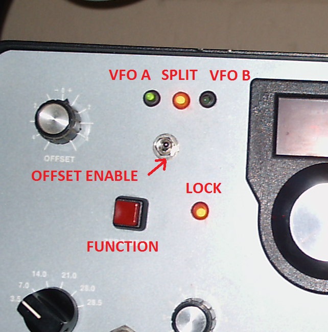
Note: If
desired, LEDs may be installed
to show the active VFO, the SPLIT function and whether the tuning is
LOCKED or UNLOCKED.
If you plan to undertake this conversion, kindly read through
the procedures described in this website before
starting the actual work.
2. Conversion Steps - Schematic - - - Itemized
Component List
a)
Preparatory
- Unplug your working radio from the AC line.
- Remove and save the (side) top and bottom cabinet screws.
There are 2 more screws on the bottom.
- Disconnect the speaker
- Remove the top and bottom covers.
- Remove all the tuning knobs, including the main tuning knob.
- Remove the front panel as described in
Section III of the service manual. You
will have to cut and tag some wires here.
- There
are 2 wires connected to the ZERO BEAT button. One runs to the digital
board and the other goes beneath the chassis. Cut the red
lead at
the digital display board and discard it, and push the other wire
underneath the chassis for subsequent removal.
b) Removing the PTO
- Carefully
remove the digital display board and move it aside. This is
done
by removing the 2 large screws / nuts on the top of the front panel and
by removing a 3rd screw underneath the chassis.
- Cut
the 3 wires feeding the PTO (including the coax). You'll
notice a
small grounding lug to which two coax shields connect.
Remove
this grounding lug and cut both pieces of coax whose shields are
connected to it. One portion of the coax runs from the PTO to
the
digitial frequency counter board, and the other runs under the chassis
to the audio board. This coax will be reconnected once the new
DDS VFO board is installed.
- Remove the two front panel screws holding the PTO and its 2
chassis screws.
- Carefully remove the PTO from the chassis, and set it
aside. You won't be
needing it anymore. Bye!
- Three (3) wires are connected to the OFFSET control. Cut them at the
control and push them - along with 2 wires and piece of coax that were
connected to the PTO - down through their feeding hole to the
underside of the chassis. Later,
they will be removed. These wires are terminated on the Control Board.
c) Installing the DDS VFO Board
- The
DDS VFO will be installed in the space adjacent to where the PTO was
located - to facilitate any adjustments and
/ or software upgrades should the user wish to undertake them.
It will be placed on a 'platform' made up of perf board
(Radio Shack), supported by 4 2 inch screws. To mount these screws, you'll
have to first remove the
audio board.
- There
are 2 screws on the rear corner of the audio board and 2 hex nuts
holding it to the front sub panel. When all the screws / nuts
have
been removed, move this assembly backward. Careful,
as the
wires are somewhat tight. Ten-Tec must have coined the 'point-to-point' wiring technique. When this has been done, the radio
should be standing on its side, with the digital readout board removed
on one side, and the audio board removed on the other.
- To
get adequate access room, remove the drive control, the electrolytic
capacitor and the S meter lamp. There's no need to cut any
wires.
- You may have to move a
terminal strip back about 1 inch to ensure that there's enough room to
mount the DDS board. So, drill a hole and move it.
- Fabricate
a perf board 'platform' large enough to mount the DDS VFO assembly and
accommodate the 4 mounting screws that will be secure it.
- Drill 4 holes through the 'platform' near the corners and
then drill the 4 mounting holes in the chassis.
- Install
the 4 mounting screws through the side of the chassis on which the
audio board is installed and secure each with a nut and a lockwasher.
- Tape the head of each screw (to prevent shorting out with
the audio board), and carefully reinstall the
audio board and secure it.
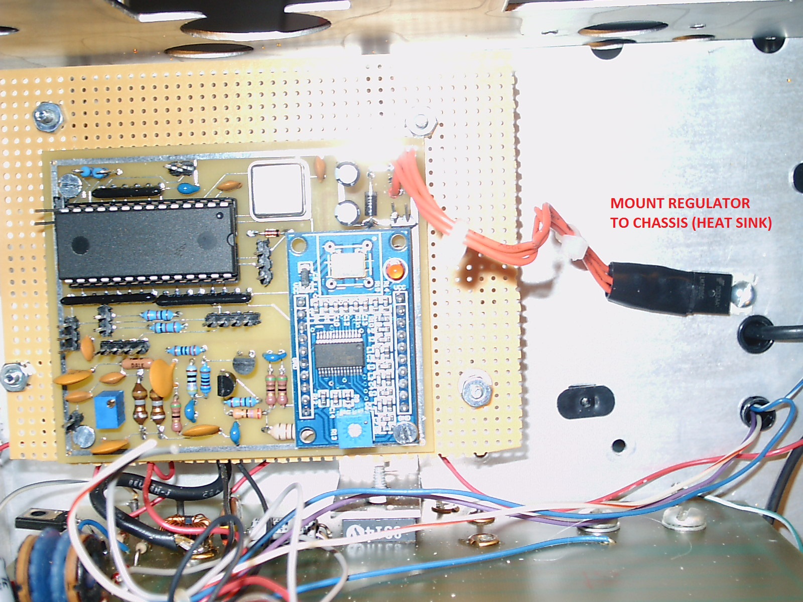
- Remove the regulator from the DDS VFO board and
'remote' it with about 6 inches of wire. Tape the
regulator connections to avoid shorts.
- Mount the DDS VFO board on the perf board platform, and
secure the platform to the 4 support screws. You can use a nut and a
lockwasher on each side of the perf board platform to secure it at the
desired height.
- Drill a hole in the chassis and mount the regulator board, as
shown here.
- Reinstall
the digital readout board.
- Connect
the severed mini coaxial cable from the digital display board to the
output and ground connections of the DDS VFO board. You can
solder the shield of the coaxial cable right to the edge mounted ground
trace (the ground for
the digital display board is delivered over the shield of the coax - hmmm!).
- Connect
another length of mini coaxial cable (RG-174) from the connection
points on the digital display board where the previously referenced
coax is terminated, and run this down through the chassis and terminate
it where the existing coax (that ran to the PTO) was connected.
In essence, you'll have a 'daisy chain' that runs from the
DDS
VFO, to the digital display board and then to the audio board.
- Remount the drive control, the meter lamp and the
electrolytic capacitor that were previously removed.
- Connect 12 VDC from the meter lamp to the DDS VFO board.
- Apply power and verify that the meter lamp and the LED on
the DDS VFO both light.
- Verify
that the Century 21's digital readout displays something, but since the
encoder has not been connected, you won't be able to tune any stations.
- Connect a 'scope to the DDS VFO's output and adjust R5 for
approximately 2 volts, peak-to-peak.
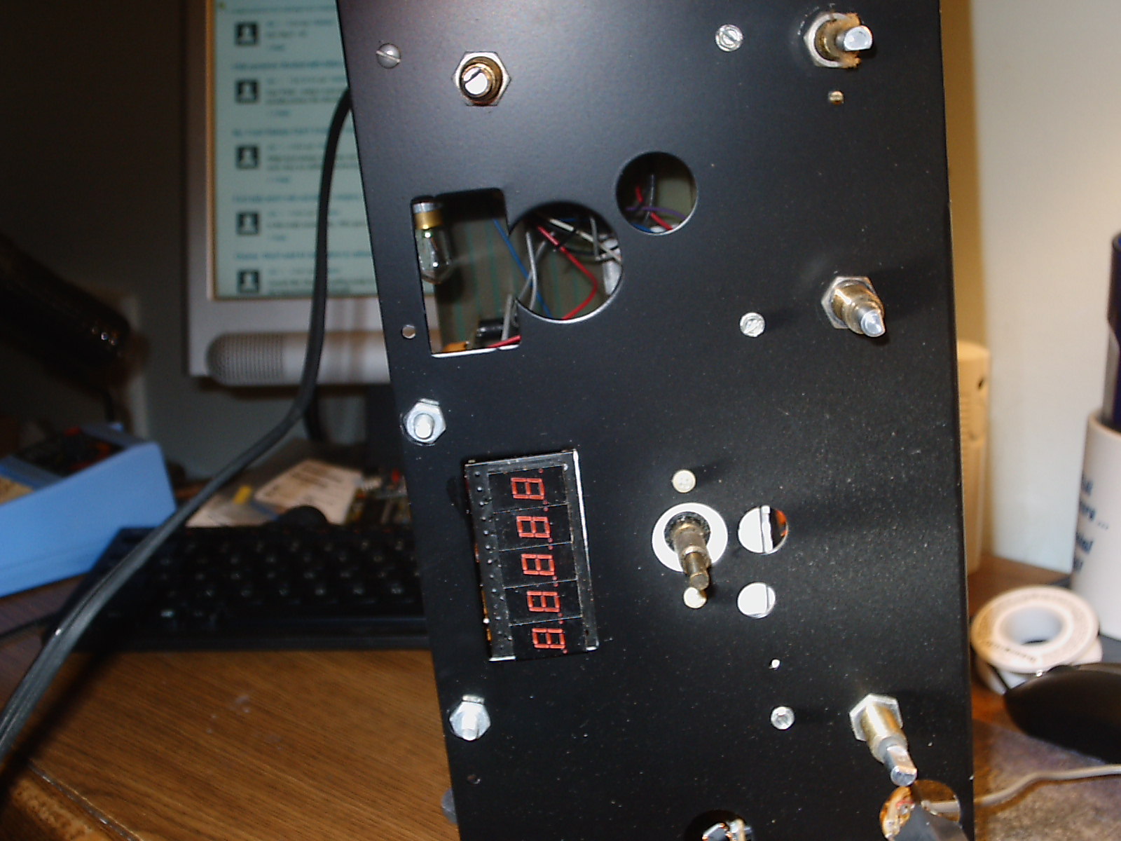
d) Mounting the Optical Encoder
The length of your
optical encoder shaft matters.
The easiest way is to place a small
metal plate (drilled
out for the outside
diameter of your encoder
and mounted in the existing
PTO mounting holes) on the outside
of the radio's sub-panel. Temporarily install your encoder
(finger tight) and then the front panel. If you can
satisfactorily attach the tuning knob of your choice, and if it spins
properly - that's great. Chances are - though - you will not
be
that fortunate. Your encoder shaft is probably not long
enough,
so either a shaft extender or some 'metal work' is required.
To use the tuning knob of my choice
whose set screw was too far
back to securely grasp the optical encoder mounted on the sub-panel,
I mounted the encoder on the back of the front panel by securing it to
a piece of scrap
aluminum.
I drilled 3 holes though the front of the panel to attach
this
plate. The tuning knob nicely hides the screw heads.
Since the optical encoder (when mounted to the front panel) didn't fit
into the PTO opening, I had
to enlarge
the sub-panel opening using a Greenlee chassis punch.
Hint:
While I modified the sub-panel while it was still on the radio, it
would be considerably easier removing it from the chassis.
This
way, a small jig saw or a nibbler could be used. Also,
another
hole needs to be drilled in the sub-panel to accommodate the OFFSET
switch. If I
convert another Ten-Tec radio, I'll be sure to remove the sub panel
first.
e) Modifying the Front Panel
At the very least, one additional hole will have to be drilled in the
front
panel for the OFFSET ON / OFF switch. I used a Radio Shack
miniature SPST toggle, and mounted as shown in the picture. As
noted above, a corresponding hole needs to be made in the sub-panel.
If you plan to use status LED's, there are several ways to mount them.
For openers, miniature LED's could be mounted in small holes
drilled through the red lense just below the digital display. If
I had it to do over again, this is probably what I would do.
However, I simply drilled 4 small holes in the aluminum front
panel into which I inserted grommets.
Note: The LED's
themselves are
inserted through the grommets and secured with a drop of crazy glue.
With the LED's placed and the
preliminary wiring work done,
the front panel may be secured to the radio so that the conversion may
be completed
 .
.
f) Connecting The Front Panel
Referencing the connection points found here,
make the following connections (fishing
the wire through an
existing sub-panel hole and under the digital display
board):
- Connect the center lug of the OFFSET control to the center
lug of the RIT connector on the DDS VFO board.
- Connect the other lugs on the OFFSET control to the right
and left RIT connections on the DDS VFO board.
- Turn the radio on and move the OFFSET control.
The displayed frequency should change. If
it changes in the proper direction, you may move on. If not,
just
reverse the end connection points on the DDS VFO board.
- Using your meter,
determine which end connection on the OFFSET control is grounded.
Once you have determined this, connect this lead to both the
push
button and to the RIT Disable switch
(one terminal connection on each).
- Connect the other side of the push button to the DDS VFO
board.
- Connect the other side of the OFFSET / RIT Disable switch to
the DDS VFO board.
- Connect the VFOA, VFOB, SPLIT and LOCK LED's (if used) to
their respective connection points on the DDS VFO board.
- Connect the LED power to the +5VDC encoder connection point.
- Verify that you can change the VFO status by momentarily
depressing the push button.
- Connect the 4 leads for the optical encoder to their
respective points on the DDS VFO board.
- Verify that the optical encoder - when turned - will vary
the frequency shown on the Century 21's digital frequency display.
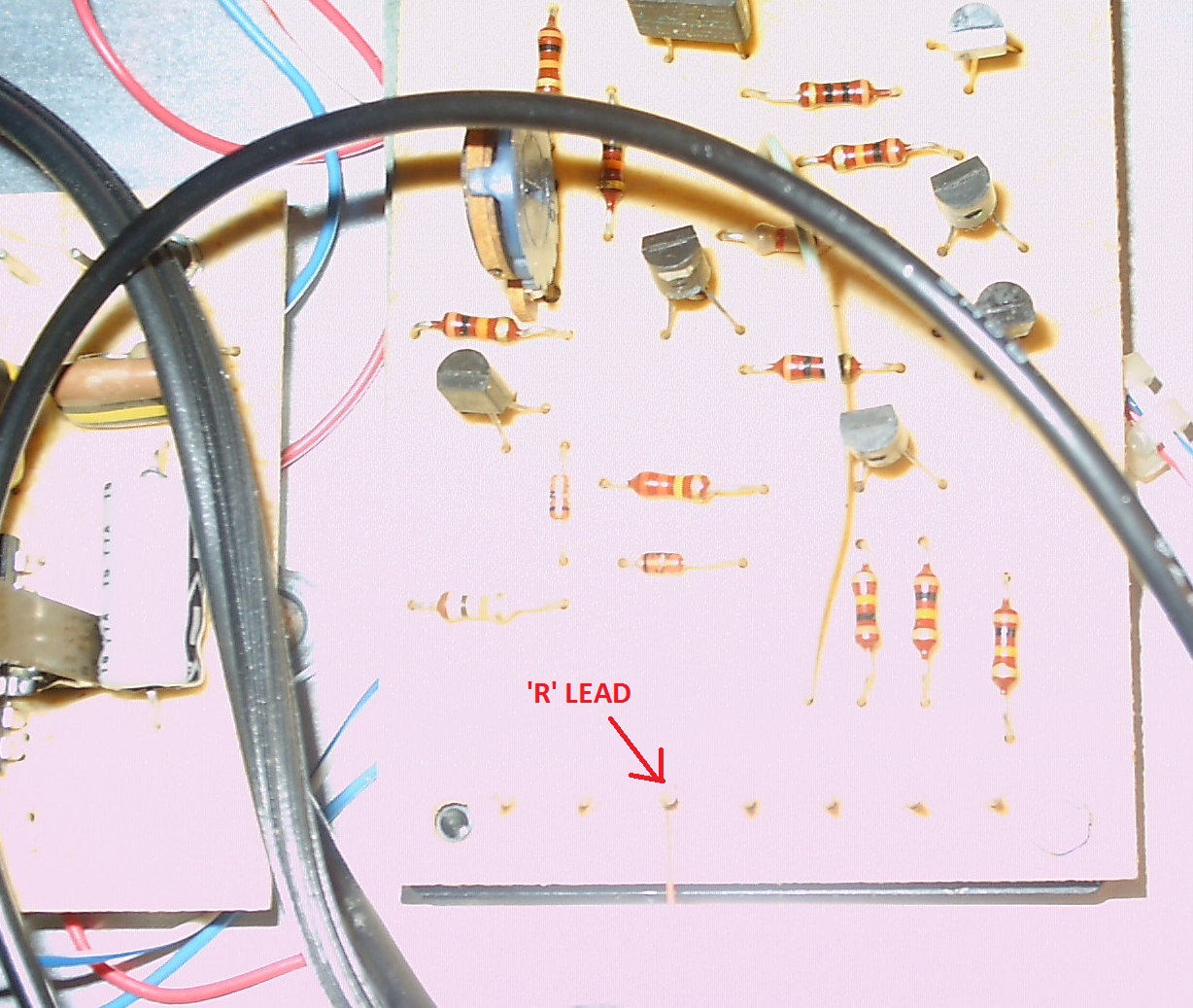
- Connect
the TMIT pin on the DDS VFO board to the R lead on the Century 21's
Control Board, as shown here. When
making this connection, please
be sure that you have identified the correct DDS VFO pin as there is 12
VDC on this lead when the Century is receiving.
- Reconnect the meter and the SET DRIVE controls.
g) Alignment Suggestions and
Other Considerations
Follow the instructions in the service manual to
adjust
the 2 variable resistors that set the current trip level.
This
requires an adjustable high wattage resistor and will ensure that your
finals will last. (I
have such a resistor if anyone would like to borrow it - I want it
back).
After making these two adjustments, I found that the 80 meter output
power (before tripping) was close top 38 watts - not too shabby.
To adjust the timebase on the digital display, turn the OFFSET control
to OFF and transmit a low level signal into a dummy load.
Using
an accurate frequency counter (or the station transceiver, for that
matter), adjust the Ten-Tec's time base until the two frequencies match.
On the underside of the radio there are 3 ground straps that are
soldered to the heterodyne oscillator board. Make sure that
these
solder connections are firm as an open on one or more of these can
cause erratic operation and noise. Just one of mine was
intermittent.
On the higher frequencies, the digital frequency counter may 'whine' a
bit. This is apparently a known Ten-Tec quirk of the digital
Century and some of the older Omni radios, as well. While
this
was not objectionable for me, others may feel differently. A
simple solution is just to switch to the two higher selectivity
positions and - presto - no more whine!
3. DDS Commands
When
initially powered up, both the A and the B
VFO
will
be set to the lower band edge, that is, 7000, 3500, 1800, 28000 (etc).
VFO A will be enabled. The user may then tune with
VFO A in
the normal manner, and VFO A will be used for transmitting.
The receive frequency will vary
based upon the OFFSET's control setting (if enabled); the transmit
frequency will not change.
To switch to VFO B, depress (tap) the previous SPOT
button briefly, and
the
system will be using VFO B. The frequency previously stored
in
VFO A will not be changed.
Note: if you have wired up the optional LEDS, the LED for
either VFO A or VFO B will be illuminated.
To enter the SPLIT mode, just tap the function / SPOT button
twice (a short followed
by a longer tap - like a
' A' in CW) and the radio will enter the
SPLIT mode. The on-line
VFO
will control reception, while the off-line VFO will control
transmitting.
Note: if you have wired up
the optional LEDS, the SPLIT LED will be illuminated.
To exit the split mode, tap the function / SPOT button twice (another
short - long tap sequence) and the
radio will revert to the normal mode. The contents of the
on-line
VFO will be copied into the off-line VFO.
To
LOCK the system at any point, just hold the function / SPOT button down
for 2 seconds and the system will be LOCKED, and cannot be changed
until UNLOCKED. To unlock the system, just tap the function /
SPOT button - and that's it! While LOCKED, the OFFSET control will work.
Note: if you have wired up
the optional LEDS, the LOCK LED will be illuminated.
If you are willing to drill another hole
in the front panel, an
optional button
may be added dedicated
to the SPLIT
function. Tap
it one time and the SPLIT function is active. You can then
use
the main button to switch between the VFO's. Tapping the
SPLIT
button again will disable the split function and map the on-line VFO
into the standby unit.
To store the last used
frequency before powering down the radio, just operate the LOCK
function,
release
the button and push and hold it again within
one second and then release it.
If you have equipped the LED's, they will all flash 3 times
to
indicate that the frequencies (VFO-A, VFO-B and the split function)
have all been stored in flash memory and will be available whenever the
radio is next
powered up.
4. Other Concerns / Considerations
If the user decides to tune up the
antenna to make
a QSO
(say, answering a CQ), and if the antenna SWR is too high - the power
supply circuit breaker will trip. Since the DDS board is
powered
by the same supply, the desired frequency will be lost when the breaker
is reset. This
is one of the drawbacks of using DDS in lieu of
the analog PTO when the DDS is
powered by the current sensing power supply.
Two solutions are possible.
- The DDS board could be powered separately
-
say by a wallwart supply -
and left on all the time. This way, should the Century's
power
supply trip out, the desired frequency information will be retained on
power up. Gauche? - yes, but workable.
- Alternately and preferably, the operator may gradually
increase output
power (using the drive control) when tuning up to an antenna.
5.
Spurs
A few DDS spurious signals that can be heard above the
background noise with a tuned antenna connected:
- 3600 khz, 7142 khz, 14000
khz, 14142 khz, 21052 khz, 21333 khz, 28012 khz and 28111 khz
6. Digital Display Whine
There are signals from the digital display at 7291 khz and 28.411 khz.
- and possibly others. Since the extraneous signals from the
digital display were few, no attempt was made to ameliorate them as
they must exist in the stock, unmodified digital Century 21.
There as also a subtle (but audible)
whine present on all bands, but most pronounced on 40 and 80
meters. While it could easily be eliminated by switching in the
CW audio filters, some folks might find it objectionable when the
receiver is running 'wide open'. Here's what I did to significantly reduce it.
For openers, the Century 21 digital display board is not shielded (like
the ones in the Omni's and other rigs) nor is it - in my opinion
properly grounded The single point of ground is actually the
shield of the coaxial cable feeding it.
Note: I think the 'Tennessee Techs' screwed up on this one.
I soldered 4 short #22 wires at the corners of the board
(underside) and a 5th right at the ground connection of C12, and
then connected these leads to the two front panel ground screws that
hold the digital display mounting plate. I screwed the nuts very
tightly. Almost of the whining noise has evaporated.
Another way to 'peel this onion without crying' would be to
ground all 4 corners of the display board directly to its mounting
plate. This would necessitate drilling out the existing insulated
mounting pillars and then replacing them with 4-40 hardware and spacers
so that the LED's would mount at the proper level relative to the front
panel. This is probably a better solution, but is also more work
- diminishing returns??
A more elegant solution might be installing an AADE DFD1A to replace the Ten-Tec digital display (after its MK50398 chip fails) and / or use the DFD1A to 'digitize' an analog Century 21 - with the stock PTO or with the DDS VFO as it would work with either one.
Food for thought (if anyone's hungry).
dit...dit