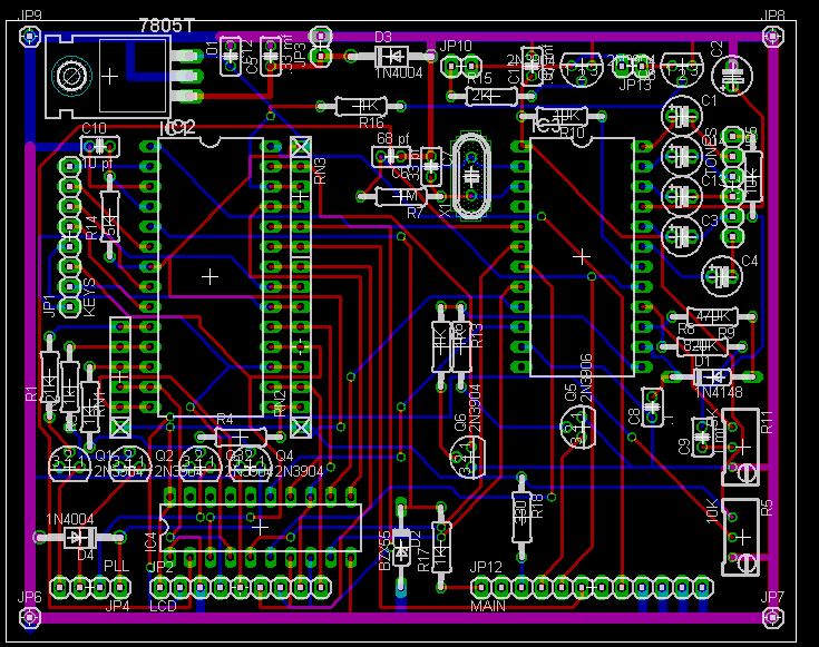
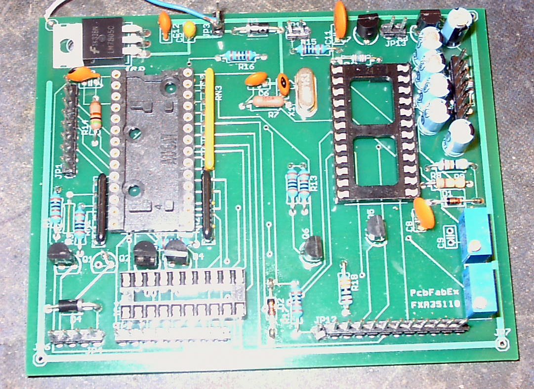
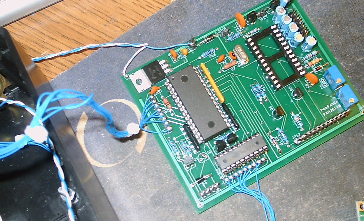
This board facilitates the conversion of GE series commercial radios for 'frequency agile' use. As such, it contains the Microprocessor, the CTCSS encode / decode functions, and the buffer transistors to interface with the 'target' radio. The circuitry is contained on a high quality, silk screened, solder masked, two sided board measuring 3 by 4 inches. The P/C board contains its own 12VDC to 5VDC voltage regulator (LM7805).
Sequential construction steps are shown below along with descriptions of each of the components. Components are installed in 'groups', as shown::
Before Starting|
Component / Value |
Function |
Comments / Action |
| 28 Pin IC Socket | MC908JL16CPE | Ensure That ALL pins route through the board. |
| 24 Pin IC Socket | MX-465 CTCSS | Ensure That ALL pins route through the board. |
| 20 Pin IC Socket | 74HC373 | Ensure That ALL pins route through the board. |
| JP-13 PWR Main - Pin 2 | +5VDC Output | Powers Logic Circuits |
| C5 - .33 mf | Decoupling capacitor | Tantalum |
| IC-2 | +5 VDC Regulator | A TO-220 device is required. |
| C1 - 10 pf | M/P Clock | Don't Change Value as Timing Loops are Involved |
| D3 | Reverse Polarity Protection | Please don't omit. |
| R14 - 5K | M/P Clock | Don't Change Value as Timing Loops are Involved |
| C11 - .01 mf. | Smoothing capacitor | - |
| JP-1 - (KEYS) | Keypad Interface | 8 pin terminal strip |
| RN-3 - (5) 22K Network | M/P Pull Ups | Strip Resistor - Check 'dot' common side - if in doubt, verify with meter. |
| RN-2 - (8) 22K Network | M/P Pull Ups | Strip Resistor - Check 'dot' common side, as above. |
| RN-1 - (5) 22K Network | Strip Resistor Network - Check 'dot' common side, as above. | |
| R1 - 1K | Current limiter | - |
| R2 - 1K | Current limiter | Needed for MVS conversion only - strap out for others. |
| R3 - 1K | Current limiter | - |
| R4- 1K | Current limiter | - |
| Q1 - 2N3904 (NPN) | SPI Enable | - |
| Q2 - 2N3904 (NPN) | SPI Clock | Needed for MVS Conversion only - strap base to collector if otherwise. |
| Q3 - 2N3904 (NPN) | SPI Data | - |
| Q4 - 2N3904 (NPN) | Transmit | - |
| D4 - 1N4001 | Reverse Surge Protection | Protects Q4 from an EMF 'spike' when PTT is released - DON'T OMIT |
| C12 - .01 | +5 VDC Smoothing | - |
| JP-4 - (PLL) | Terminal Strip | Connects SPI and Transmit to Radio. |
| JP-2 - (LCD) | Terminal Strip | LCD Connections |
| D2 - 5.1 Volt Zener | M/P Protection | Limits COR / CAS voltage to M/P - protects M/P - DON'T OMIT |
| R17 - 1K | Current limiter | Limits current on COR (CAS) lead prior to D2 clamping action. |
| JP-12 - MAIN | Primary Radio Interface | Interface connections to radio. |
| R18 - 1K | Current limiter | Tone Detected LED |
| Q5 - 2N3906 (PNP) | Tone Switch | Lights tone detected LED |
| Q6 - 2N3904 (NPN) | Tone Detect Scan | Alerts M/P of detected Tone During Tone Scan. |
| Q7 - 2N3904 (NPN) | PLL Unlock Inhibitor | Blocks Transmit Override function if radio's PLL is unlocked. |
| Q8 - 2N3904 (NPN) | Transmit Override | Insures that the target radio will transmit when requested to do so (if PLL locked) |
| C9 - 1 mf | Coupling | CTCSS Out |
| JP-13 | Terminal Strip | To be strapped later if the radio doesn't transmit reliably. |
| JP-10 | Terminal Strip | Connects PLL Lock and Transmit Override leads from radio |
| R5 - 10K Potentiometer | LCD Contrast Control | - |
| R11 - 5K Potentiometer | CTCSS Level Adj. | - |
| R13 - 1K | Current limiter | CTCSS Tone Detect Switch |
| R15 - 1K | Current limiter | Limits current flow to the base of Q6. |
| R16 - 1K | Current limiter | |
| R7 - 1 Meg | CTCSS Clock | - |
| C6 - 68 pf | CTCSS Clock | - |
| C7 - 33 pf. | CTCSS Clock | - |
| X1 - 4 Mhz Crystal | CTCSS Clock | - |
| C11 - .01 | Decoupling | Decouples MX-465 CTCSS Chip. |
| C2 - 1 mf electrolytic | CTCSS | - |
| C13 - 1 mf electrolytic | CTCSS | - |
| C3 - 1 mf electrolytic | CTCSS | - |
| C4 - 1 mf electrolytic | CTCSS | - |
| R10 - 10K | CTCSS | - |
| JP-5 (TONES) | CTCSS Connector | Tones 1 and 2 used for all conversions. - Others used in Delta Conversions (see text) |
| R8 - 560K | CTCSS | - |
| R9 - 820K | CTCSS | - |
| D1 - 1N4148 |
CTCSS |
- |
| C8 - .1mf | CTCSS | - |
Apply power (12 VDC) to the PWR - BU (JP3 - Pin 2) and ground to the VSS lead (JP3 - Pin 1).
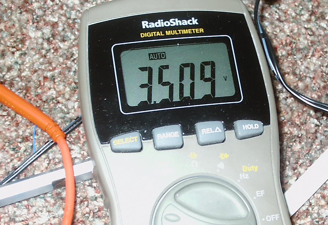
Verify +5VDC on IC-1 (M/P), pin 7, and ground on M/P pin 3.
Verify +5 VDC on M/P pins 4, 11, 13, 14, 16, 17, 18, 19, 20, 21, 22, 23, 24, 25, 27, checking for crosses.
Verify approximately .84 volts on pins 10, 12, 15, and 26.
Verify +5VDC on CTCSS chip (MX-465P) pins 1 & 18, and on CTCSS Latch (74HC373) pins 20 & 11. Verify ground on pins 1 and 10.
Verify +5VDC on the LCD terminal strip (JP2) pins 1, 4, 5 , 6, 7, 8 and 9. There will also be some positive potential on JP2, pin 2, depending upon the setting of the LCD Contrast Control - R5. Adjust R5 and verify voltage change on pin 2.
Verify +5 VDC on MAIN (JP-12) pins 3, and 6. When done, switch off the power.
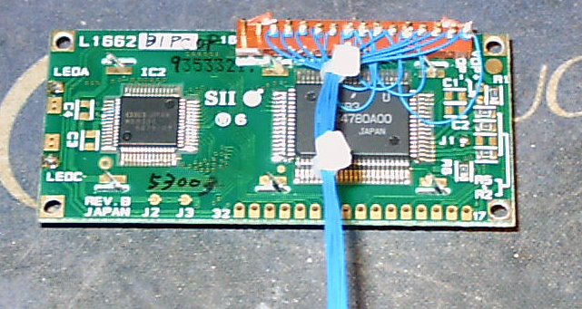
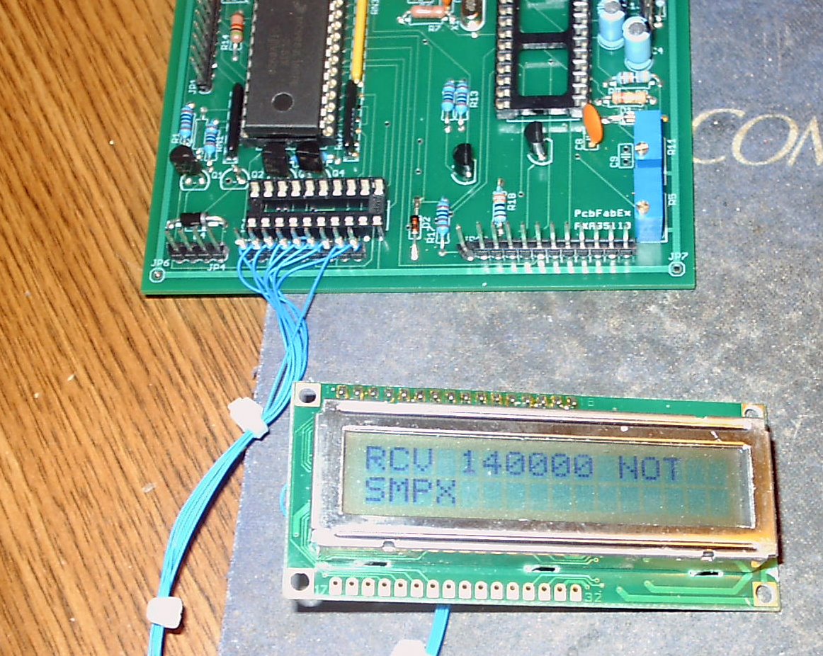
Connect the 2x16 LCD display. (Any LCD with the HD44780 controller will work). Don't remove any protective plastic strip (if so equipped) from the front until the LCD is mounted and you are ready to place the bezel / plexiglass over it.
If not already equipped with wire wrap pins, solder wire wrap pins (short pieces of stiff wire) to each of the LCD's connection points. Don't use too much solder as this could 'contaminate' the display. These will be used to connect the LCD's inputs to the P/C board. Check for 'shorts'.
Next, connect LCD pins 1, 5, 7 ,8, 9 and 10 together using 30 gauge wire. This sets up the LCD for 4 bit operation and serves as a ground.
Determine the length of the wire required to connect the LCD in your control head to the M/P board which will probably be mounted on the rear of the enclosure. Leave enough wire for subsequent servicing.
Connect the LCD to the P/C board using 30 gauge (wire wrap) wiring. Before applying power, check for crosses between any of the adjacent pins on the LCD display, and that the +5VDC (VCC) lead is connected to LCD pin 2, and that ground (VSS) is connected to pin 1.
Also, determine the value of the LCD backlight resistor. I've used resistors between 82 and 100 ohms. Check here for additional information. Encapsulate the backlight resistor in heat shrink tubing.
c) Connecting the Key Pad - An Integrated Unit is a Good Choice
Make the 8 wire wrapped connections between the P/C board and the keypad. Here are some suggestions on determining the correct pin-outs for those surplus / unmarked keypads..
Before installing the chips, apply power to the P/C board and verify that the LED inside the LCD lights. Adjust the contrast resistor until you see dim rectangles across the top of the first row of the LCD.
With the power off, and following CMOS handling precautions, remove the M/P from it's protective conductive foam. Ensure that all pins are straight, and carefully insert the M/P into its socket, 'rocking' it side to side. Install the MX-465P CTCSS and the 74HC373 CTCSS latch chips.
Note: You'll have to ensure that the pins on each of the integrated circuits are perpendicular to the IC proper so that they will seat properly in the socket. A good way to make this alignment is to hold the IC pins against your workbench while aligning the IC perpendicular to it. This aligns all the pins on one side at the same time.
Also Note: The 'notch' on the M/P and MX-465P chips is at the top of the board. The notch on the CTCSS latch chip faces D4.
Operational Tests - For All Frequency Applications
Turn the power back on. The LCD will briefly display the current software version (V0.01). Adjust the LCD contrast control (R5), as required.
Connect
the Tone Detect LED. Since - on power up - the M/P will
deactivate the tone output, the LED should be lighted. This will
help you determine the proper LED polarity. This is normal.
If the LCD displays KEY!, you've simultaneously depressed two keys. Or the wiring between the keypad and the M/P board may be incorrect. Valid keystrokes are closures between ONLY TWO LEADS, one in the row, and the other in the column group. Recheck your wiring. If you have a Key Error, use the D Key to clear it.
Enter another frequency between 140 and 184 Mhz. For the VHF and UHF, it is not necessary to enter the leading digit (i.e, the 1 or the 4). Since only 5 khz. steps are allowed in the VHF mode setting, the M/P won't accept anything beside 0 or 5 as the last digit. If another digit is entered, the M/P will overwrite this entry to a 0, and set the frequency. Similar logic applies to 12.5 khz (UHF).
Note: 'Stepping' the frequency up and down is done by either the * or the # keypad keys.
Ground the Mike PTT lead and note that BAND shows on the LCD. This means that the transmission is not allowed, unless a frequency between 144 - 149 Mhz has been entered. The program allows transmissions only on authorized USA amateur frequencies.
DISCLAIMER - - If you follow the steps outlined herein, you do so at your own risk. I cannot, nor will not, be responsible for any possible damage to radio equipment, personal property, to yourself or to others caused by modifications that you may make to the radio as a result of your reading this.
The M/P controls TRANSMITTING as well as receiving on many frequencies, suitable for a wide range of HF, VHF and UHF needs. In the USA, TRANSMIT operation requires a license issued by the FCC for the class of operation intended. Amateur radio licensees must maintain strict control over their equipment, preventing unlicensed operation within the amateur bands, or outside of them.
Copyright 2000 - 2010 - K3JLS