Upgrading the Ten-Tec Argosy
Achieve better noise floor and "crunch-proof" performance
Scanned from: Ham Radio Magazine, Pages 38-50, November 1986
By
KW7CD
Previously: WB3JZO
CORNELL DRENTEA
757 N CARRIBEAN AVE
TUCSON AZ 85748 USA
This article proves two things: first, that outstanding results can be obtained by choosing inexpensive, well designed equipment and second, that there's still room for hams to make worthwhile improvements to their transceivers. Owners of the original Ten-Tec Argosy who'd like to hear weak signals in the presence of powerful adjacent signals without "popping" and intermodulation distortion may find it especially useful.
With several thousand in operation around the world, the Argosy is particularly attractive for the CW QRP operator. It can also serve as a low-cost base station transceiver which can drive a high-gain linear amplifier to 1000 watts output on most bands.
Although my Argosy was a good performer in many respects, I decided that it could be improved. For example, with DX propagation only marginal (given the current sunspot cycle), its noise floor was so high that DX signals of S3 (approximately 0.8 uV rms in a 50-ohm system) and below were obscured. In addition, the receiver desensitized 100 kHz away from a signal generated by a station located no more than a mile from my QTH.
The modifications described here will improve the noise floor, compression point, intercept point, and AGC characteristics of the Argosy receiver, as well as the transmitted characteristics of its SSB signal. They will also add digital versatility to the unit by replacing the analog dial with a precise four-digit display capable of reading the transceiver's frequency with an accuracy of +/- 10 Hz.
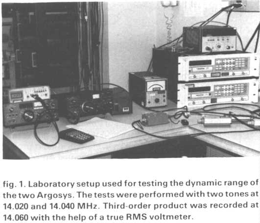
Critical listening and laboratory tests comparing a modified Argosy with an unmodified one have shown that these modifications result in significant improvement (fig. 1). The test results (table l at the end of the article)show clear improvement in the areas of minimum discernible signal (M DS); two-tone, spurious-free dynamic range(SFDR); and blocking dynamic range at only 5 kHz from the interfering signal, with the latter showing an impressive 30-dB improvement over the unmodified Argosy. After the modification, on-the-air tests allowed copy of weak CW DX stations of S3 and below as close as2. 5 kHz from WB0NHD, less than a mile from my QTH and running a full kilowatt with his antenna pointed in my direction !
While some of these changes were communicated to the manufacturer and reportedly incorporated in the production of the recently released Digital Argosy, owners of this unit may wish to perform those modifications not implemented by the manufacturer.
The changes described in this article are within the reach of any technically inclined Amateur and can be implemented totally or partially as desired. However, I recommend that you have a good understanding of how the Argosy works before proceeding with the modifications. I've tried to describe the modifications in sufficient detail here; because of limited time, neither Ten-Tec nor I will be able to provide additional information. For a better understanding of this article, it would be wise to read the owner's manual as carefully as possible.
Improving the noise floor
As previously stated, one of the most annoying problems associated with my Argosy's receiver performance was its high noise floor that obscured weak stations. While this was not apparent on strong signals, the hiss greatly reduced the overall intelligibility of many CW and SSB signals.
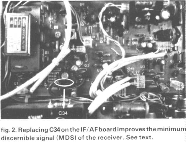
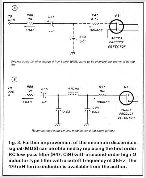
Several calls and a face-to-face discussion at the Dayton Hamvention with Ten-Tec engineers offered some possible solutions After several unsuccessful trials, I proceeded on my own to find out what was wrong with the receiver. A few hours of analysis and careful isolation of stages revealed, much to my surprise, that the problem was caused by a design glitch in a totally different area of the receiver. The audio low-pass filter (R47, C34 following the product detector, Q3, which is located on the I-f/af board 80785) had a corner frequency of 3.28 kHz, which would have been a good choice if attenuation were steep beyond this point. However, this was only a simple first-order low-pass filter with an attenuation slope of 6 dB per octave, which was incapable of preventing BFO noise sidebands of up to 10 kHz from spilling into the high gain audio amplifier of the receiver after being mixed down to audio frequencies in the product detector. This, in turn, superimposed an annoying hiss over all the received signals and obscured signals below S3. Once the problem was found, the fix was simple. Changing C34 from 0.01 to 0.1 started the corner frequency of the low-pass filter at 338 Hz, allowing enough roll-off beyond 3 kHz, canceling the annoying noise and making a dramatic improvement in the signal-to-noise performance of the receiver. Although one might suspect that the 6-dB roll-off of the new filter with a corner frequency of only 338 Hz might affect the overall audio response of the receiver, this was not the case. The audio frequency response measurements performed after the modification was made showed a flat response over the entire audio range of interest (600 Hz to 2800 Hz).
This was due to compensation in the audio gain of the receiver inherent in the original design. With the problem fixed, the rig worked so well that I decided to share the information with Ten-Tec, whose engineers quickly calculated the new corner frequency, tested the change, and concluded that it made a "radical" difference in the noise floor performance of the receiver.
Figure 2 shows the location of C34 in the transceiver. While it's not necessary to completely remove this capacitor (one can parallel the new capacitor on top of the board), doing so involves simply removing the board -just unplug all connectors, remove all metal screws, and replace C34 with a 0.1 uF ceramic capacitor rated at a voltage greater than 25 volts. Slide the board back into place. This modification should take no more than 10 minutes. (Be careful to plug connectors back exactly where they belong.)
Even better performance can be obtained by totally replacing the RC network with a second-order filter with a cutoff frequency of 3 kHz. This involves the use of a high-Q, 470-mH inductor as shown in fig. 3. In this modification, the source resistor (4.7 k) has been replaced with a 10-k resistor, which was necessary for symmetrical C values in the legs of the filter, as well as to make use of the entire range of the volume control.
Reducing AC hum
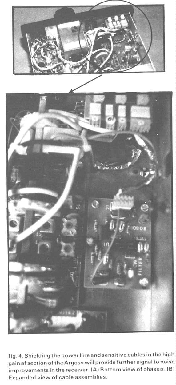
Although the receiver was now very quiet. It was immediately apparent that the next problem was a 120Hz hum previously obscured by the noise floor. This hum was caused by the ac switch and power line located in the immediate vicinity of the high-gain audio stages, unshielded audio cables, and front panel controls, all acting as audio pickups for the induced ac field.
I decided that the perfect solution - eliminating the power switch at this location - would not only solve this problem but also allow another modification: the insertion of an rf/af gain, dual potentiometer, which will be described later in this article. Good results can be obtained by shielding both the power line and the sensitive cables as shown in fig. 4. Copper foil is recommended; however, aluminum foil should also work. Make sure that the shield is grounded at several points to avoid ground loops.
Improving dynamic range
Two additional modifications were effective in increasing the Argosy's dynamic range. While they are specifically intended to improve the intercept point of the receiver, they also improve MDS performance.
The first modification consists of replacing the present mixer diode set (D12. D13. D14, and D15* on the rf/mixer board 80784) with a new set of matched high-voltage Schottky barrier diodes. The part chosen for this application was the Hewlett Packard 5082-2800. The 2800 uses a "guard ring" design, making it ideally suited for handling high-level signals.
The second modification consists of changing the rf switch diodes (D10 and D11) on the same board to high current PIN diodes designed especially for rf switches and attenuators such as the HP 5082-3081 . About 75 mA of bias current should be provided to these two diodes for a positive rf turn-on. This is accomplished by replacing the 470-ohm resistor at R4 with a 220-ohm half -watt resistor. Although the 3081 can use more current for better rf switching, this is not recommended in order to protect the drive transistors located on the Control Board 80781 . This modification is not recommended for applications requiring thrifty battery use - for example, in portable QRP operation. However, it does further improve the dynamic range of the receiver.
To implement these changes, remove all connectors and metal screws carefully and slide the rf /mixer board out. Remove the old diodes with the help of “Solder Wik" or a similar product and replace them with the new parts, following the diode polarity already marked on the board (the band is the cathode). Reinstall the board, making sure that all metal screws and connectors are back in their proper places. Readjust mixer balance trimmer C2 for minimum received product at 21.320 MHz, as outlined in the manufacturer's manual (pages 3-7). The receiver will now be very quiet and signals will stand out against the background without being disturbed by powerful adjacent stations. The AGC will also be favorably affected since less intermodulation distortion will be present in the i-f passband. Remarkable results have been realized by replacing the original four-pole i-f filter with a better filter, but some problems will occur if you try to use standard 9.000-MHz filters.
Using standard 9.000-MHz i-f filters
The Argosy came equipped with a four-pole, 2.4kHz wide filter which drew some unfavorable audio reports in SSB. In addition, a "wide" transmitted signal was reported on some crowded bands.
A similar problem noted in the receive mode
contributed to adjacent signals getting into the i-f passband and
consequently activating the AGC. While it's possible to buy
optional filters from the manufacturer, this was beyond my
financial means at the time. I tried some new 9.000-M Hz filters
with the proper impedance but found they produced unfavorable
results for no apparent reason. A careful analysis of the design
showed that the manufacturer's choice of i-f center frequency was
9.0015 MHz instead of the more popular 9.000MHz approach (this
isn’t readily apparent from either the manual or the part
numbers marked on the filters as used in the transceiver).
Because 9.0015-MHz filters were not available to me, some
ingenuity was required in order to use the more standard 9.000-MHr
filters.
In order to use these filters with the Argosy it was necessary to
change the frequency of the BFO crystal and adjust three trimmer
capacitors on the SS B Generator Board 80780 for slightly
different frequencies.
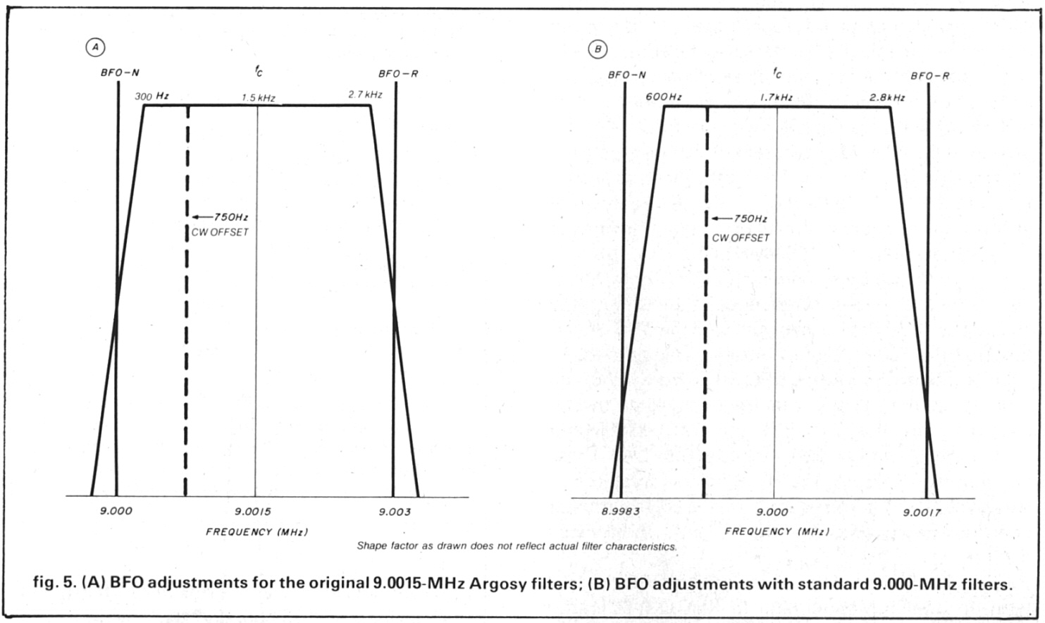
Let's analyze the way the BFO works from fig. 5A. In order to use the 9.0015 center frequency filter, the Argosy designers chose B FO frequencies of 9.000 MHz for "SB-Normal” and 9.003 MHz for "SB-Reverse." These parameters are set by frequency pulling a crystal oscillator via the triple trimmer setup on the SSB generator board according to a procedure outlined in the owner's manual.
To use 9.000MHz filters, I replaced the BFO crystal with an 8.9985MHz crystal (a KVG XF-901) and proceeded to recalibrate the three trimmer capacitors according to the Carrier Oscillator Alignment Procedure explained in the manual and by using the new parameters shown in fig. 5B. The new numbers allowed for an audio passband of 600 Hz to 2800 Hz (center frequency, fc, is 1700 Hz) when using the filters recommended in this article (see table 2). The 1700 Hz center frequency was selected over the more conventional 1500-Hz unit after a series of intelligibility tests. Many excellent reports were received after the modification.
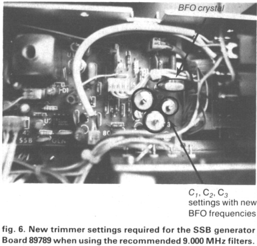
This audio range lends itself easily to the 750-Hz off set required for the CW mode. The recommended 9.000MHz filters exhibit superior shape factors over the original four-pole filter (See table 2). Figure 6 shows the approximate position of C1, C2, and C3 trimmer capacitors necessary for this modification as implemented in my transceiver.
A set of two 9.000-MHz filters can be cascaded (one replacing the four-pole filter on the rf/mixer board 80784 and the other at the optional location of the I-f/af board 80785) with exceptional results in receive or transmit. The combination is the equivalent of a 2.2-kHz wide, 12-pole filter with a shape factor of better than 1.6:1 in the receive mode (only one filter is used in transmit). When combined with the previous changes, this modification produced superlative performance which included improved AGC response in all modes and improved small signal performance in the presence of strong signals.
To make the change, construct the filter connectors by cutting two 2.4 x 1.0 inch pieces of unclad PC board material. Drill four holes to fit four 0.040-inch diameter connector pins snugly. (These pins can be made of discarded TO-5 transistor leads.) The connector pattern can be copied directly from the transceiver PC board lay out with a piece of paper and a pencil, using the pencil to punch the existing connector holes and transferring the information to the new PC boards. Drill additional holes for installing the filter assembly on the PC board as required. Then secure the four connecting pins in place at the proper height with blobs of solder on each side of the board, following the dimensions from the original filter assembly. Connect the inputs, outputs. and the grounds of the filters in the same manner as in the original filter. It's important to realize that the cascaded filter on the i-f/af board 80785 will require two dc blocking capacitors if you're using the suggested filters (0.01 pF will do) at the input and output ports because of the diode switching involved there.
After installing the filters and the new BFO crystal, perform the manufacturer's carrier oscillator alignment on the SSB generator board 80780 by using 8.9983 MHz for "SB-Normal" and 9.0017 for the "SB-Reverse" positions. Use fig. 6 as a guide to begin the setup and fine tuning of the three capacitors until no error results from the interactive effect (this modification requires a full understanding of how the Argosy BFO works). Adjust the CW offset in step 10 of the procedure to 750 Hz above the "SB-Normal" as required. Although the procedure outlined in the owner's manual is a bit confusing at first because of the interaction between the three capacitors, using a digital counter and a scope should make things easier. No matter how well the settings are performed. the BFO frequency will change value slightly over time because of environmental impact on the trimmer capacitors. Variations of plus or minus several tens of Hz are not unusual for this BFO. These variations can introduce some coloration when you're switching sidebands in either the transmit or receive modes.
To check whether the transceiver needs realignment. follow this procedure. With the receiver on and the antenna disconnected, listen for the "hiss" pitch characteristic in SB-N. If things are "equal" (which they should be), the same pitch characteristic should be heard when switching from SB-N to SB-R. A final test for a different kind of coloration (called SSB brilliance) should be performed in the transmit mode with the rf output fed to a dummy load and a microphone connected to the transceiver. To verify that your SSB signal sounds "alive" on the air, use another receiver equipped with a pair of headphones to listen to your own signal. To avoid overload of the receiver, perform the test in the 5-watt QRP transmitter position. If the signal sounds mushy, realign transformer T1 (the big can) located on the same SSB generator board while pronouncing words containing the letters “S” and “Z” into the microphone.
Using the plastic tool provided with the transceiver, slightly vary the position of the T-l core until these letters are heard clearly in the monitoring receiver (the core should be at the bottom of its travel). Repeat this test in the opposite sideband until everything sounds as lifelike as possible. Because the transformer has been adjusted at the factory, this adjustment should be minor. If it hasn’t been properly set, this can make a major difference in intelligibility of your SSB signals at the other end. (it has no effect on the receiver itself.) Last, but not least, make sure that carrier balance adjustment, R1, is set for minimum carrier leakage as pointed out in the procedure described in the manual.
Improving audio AGC characteristics
One of my biggest complaints was the popping characteristic of the Argosy's audio AGC. While most of the modifications presented so far improve to a great degree the AGC's reaction to unwanted out-of-band signals and in-band background noise, a simple additional modification will virtually eliminate popping. This change consists of replacing C12 on the i-f/af board 80785 with a 22-uF, 35VDC tantalum capacitor, which exhibits a favorable charging curve that cancels out the annoying "pop," at the same time providing a more suitable response time for the AGC. With this capacitor in place, the attack and release times were measured at 20 milliseconds and 2 seconds, respectively. This constitutes an almost perfect compromise between CW and SSB. (This modification can be incorporated when the other changes are being made to the same board.) When installing the tantalum capacitor, be sure to observe polarity. After this change, popping was almost completely eliminated with only a hint of it left on signals exceeding 40 dB over S9 in level, and with all filters(including narrow af) inserted. In order to completely eliminate the popping, the addition of the rf gain control is required RF gain control
Although the original Argosy didn't include an
rf gain control, adding one can further improve the performance
and versatility of the rig when attempting to copy weak signals
in presence of strong ones. An additional improvement is the
complete elimination of popping. (This simple matter is explained
in Ten-Tec's technical note TN2-525.) The modification consists
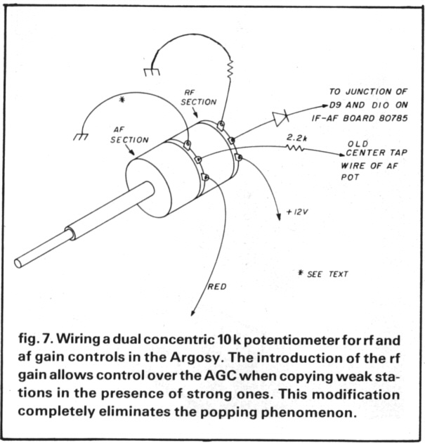
of replacing the single potentiometer used for the audio gain
with a dual concentric 10-k potentiometer. To in stall the new
control, the front panel and the old control were removed. I
soldered the wires from the old af control in the same locations
on the front section of the new dual potentiometer by also
inserting a 2.2-k carbon resistor in the center leg (the Argosy
has so much gain that only about a third of the old potentiometer
range was usable before). Then I connected the rear section as
shown in fig. 7.
This change eliminated the switch function of the af Power
control. (This can be a good move because you won't need to worry
about induced hum into the af sections any more. ) The rig may be
switched either from the front panel of the power supply or by a
miniature switch added to the back panel. If desired, an AGC on/off
switch can also be installed by breaking the connection between D9
and Q5 on the i-f/af board 80785 and wiring in another miniature
switch. I chose not to implement this modification permanently
because it wouldn't add anything to the performance.
Because concentric knobs weren't available, they were fabricated. The af knob was made by cutting off the top of a regular knob with a diameter of 0.8 inch. Additional filing brought the set screw within immediate proximity; little shaft length was available because of the spacer effect of the front panel. The rf knob was fabricated from a smaller diameter knob with the 0.25-inch hole filled with epoxy and redrilled for the inner shaft, which measured 0.125 inch in diameter. The entire modification took half an hour to complete.
PTO frequency stability
Another annoying problem related to the Argosy's performance was the frequency instability of the PTO, which caused small, sudden jumps of a few tens of hertz in the received or transmitted signals. This phenomenon seemed to be intermittent and showed up at random times with no apparent remedy. The problem, confirmed by other Argosy owners, may be present in similar rigs.
While the problem appeared mechanical at first. I concluded that it was caused by an intrinsic characteristic of a part in the design of the PTO. I was happy to find that Ten-Tec offers - on an exchange basis and for a reasonable fee of $25 - a new PTO that doesn't exhibit the problem. When a new PTO was obtained and installed, the problem disappeared once and for all.
The installation requires the removal of several wires and PC boards, but shouldn't take more than 15 minutes to complete. The performance of the new PTO is well worth the investment and allows the use of a precision digital counter which displays the transceiver's frequency with a resolution of 10 Hr, a considerable improvement over the +2kHr calibration provided by the Argosy's analog dial.
High-resolution digital display
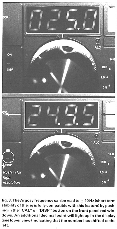
The static digital display design in the modified Argosy uses three ICs and does away with the multiplexer noise so familiar to other designs. It allows the use of the front panel push button previously used to turn on the calibrator to further increase the resolution of the displayed frequency to 10 Hz, a feature I found extremely helpful.
The top-notch performance of the modified Argosy was finally complemented by the installation of a static (non-multiplexed) four-digit counter which displays the frequency of operation by reading the premixed PTO/ crystal oscillator's frequency. Reading the premixed injection presents the advantage of accounting for all possible shifts created in the crystal oscillators, which would have to be accounted for mathematically if reading only the PTO frequency. On the other hand, such a counter must be capable of operating at frequencies better than 20 MHz(as opposed to 5. 5 MHz) if measuring the PTO. In addition, by wiring the calibrator push button from the front panel as shown, the four-digit numbers can be shifted to the left, allowing for 10Hz resolution (an additional decimal point lights up to indicate that the magnifying feature is turned on). See fig. 8.
The design of the display was inspired by intersil application notes. I had initially hoped that an LCD display would fit under the Argosy's front panel, but this was impossible because of the rather small dimension between the top of the bezel and the display opening. In addition, the 16-kHz back plane oscillator called for in this design was out of the question because of rf noise. The resulting design uses a static seven-segment LED design based on the ICM7225 LSIC from the same manufacturer.
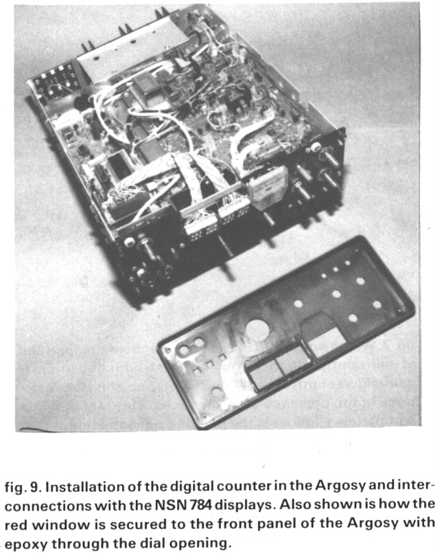
While many seven-segment LED displays were available, I chose the National NSN 784 common anode display because of depth restrictions between the front panel and the sub-panel. The 784 is built without pins and space-consuming extruded parts. Its design is basically a square PC board with the LEDs fused into the surface of the board, allowing for minimal depth which fits snugly between the two panels. With this approach, the flat cable used to connect the display with the small digital board located in the transceiver fits nicely through the narrow window previously used for the analog dial as shown in fig. 9.
After this wiring was completed, the socket pins from the signal-conditioning IC74HC4049 and from the controller/oscillator ICICM7207 were shortened for better frequency response. If not short enough, pins on the 74HC4049 socket will limit the frequency response of the counter on the higher bands. As a matter of choice, the front panel switch (CAL) can be used either for turning on the display or for the magnifying feature. Both choices are shown in the schematic diagram in fig. 10. Only one function is possible without the addition of a separate switch
The rf injection signal is fed to the conditioning IC74HC4049 via a coaxial cable and a 100-pF capacitor from connector 31 located on the rf/mixer board 80784. When soldering at the connector, make sure not to ground the shield of the coaxial at this point or you'll defeat the turn-on function of the front-panel switch.
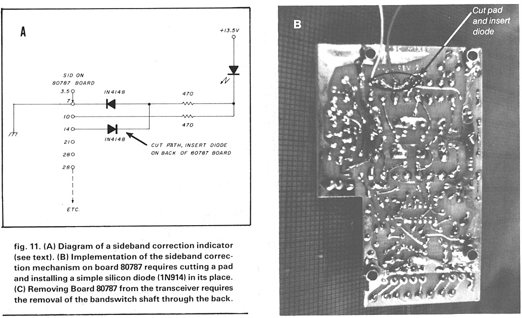
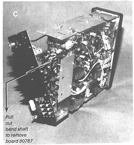
Adjusting the display is easy when using a high resolution counter connected to the same pin on connector 31. Adjust the trimmer capacitor on the ICM7207 for an equal frequency readout between the counters, which should both be set in a high resolution mode. If a counter isn't available, reasonable results can be obtained by tuning to WWV. This counter will read only the center frequency of a station as offset by the B FO modifications performed earlier. If you’re using the recommended settings, you'll have to add 1.7 kHz in lower sideband and subtract 1.7 kHz in upper sideband. Be cause no preset lines are available in this simple design. A feature activated from the band switch can tell the user when to add or subtract the offset number by lighting up either a plus sign or a minus sign inside the last digit of the display. This was accomplished by cutting a pad and installing a diode in its place instead on the S1D switch from board 80787 as shown in figs. 11A, B, and C.
Installation of the digital display in the Argosy proceeds as follows. Obtain two NSN 784 dual displays and grind off the rivets holding the windows to the back of the PC boards. Carefully remove the windows and plastic inserts so as not to touch the fused LED’s on board, now visible to the eye. Deposit a few drops of "Super Glue" or equivalent on the board in areas outside the segments and LED locations and key back the plastic insert without the window. Squeeze the assembly together until the two parts become a single assembly. This will prevent possible damage to the LED’s. Repeat the operation for the second display. Then solder a 16-wire flat cable to each of the boards as shown in fig. 10. Remove the front panel from the Argosy and remove the existing red window as well as all mechanical cables and fixtures associated with the analog display. File out the square opening in the front panel to accommodate the two new windows. Fit the two square windows snugly in the opening until they're flush with the outside surface of the front panel. Then deposit a small amount of epoxy around the perimeter of the two squares inside the front panel. In the process, make sure that the two windows are flush with the outside of the front panel; this is accomplished by laying the entire assembly on a flat surface. Only a small amount of epoxy should be deposited so that the PC board LED assemblies can fit back in their rivets when the job is complete. No epoxy should be allowed in the area under the top of the front panel because the cover must be free to slide back under the bezel.
To complete the job, wrap electrical tape around the metal cutout to prevent possible grounding. Place a weight on Top of the front panel assembly and allow it to cure overnight. When curing is complete, reinstall the Argosy's front panel by pulling out the ALC indicator diode assembly and plugging it properly into the red LED from the front panel. Then carefully insert the two seven segment LED boards in their keys, which are now attached to the front panel. Make sure that the translucent plastic diffuser squares are sandwiched between the red windows and the PC assemblies. Then pull things together until the digits are visible through the front windows. Push back the entire front panel assembly until the ALC LED fits back in its hole and screws can be attached. The flat cables can now be bent and properly wired to the digital board. To complete the job, make a 0.25 inch deep cutout in the top cover for the entire length of the display in order to prevent possible shorts. As an additional precaution, place electrical tape along the cutout.
Conclusions
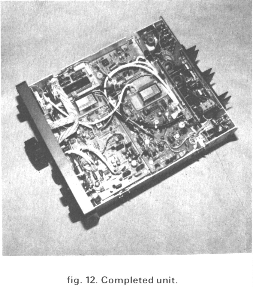
The modified Argosy (fig. 12) has been in operation for several months. Its performance has been a pleasure and well worth the efforts described in this article. Other possibilities exist for modifying the Argosy to increase its versatility. These include adding a separate PTO with memories; an rf splitter in the receiver input to allow for a separate receiver to be used in conjunction with the transceiver (this can be done by breaking the coaxial cable from connector 32 and introducing a Mini Circuits PSC2-1 rf splitter in the circuit with one of the outputs wired to one of the empty RCA connectors in the back of the transceiver); passband tuning in the I-f, and even a new BFO circuit. A list of parts available from the author and from various suppliers is shown in table 3 below.
Acknowledgments
I would like to thank Tom Jorgensen, K0UBF, for donating his unmodified Argosy for the laboratory tests; Marc Denis, KD0QO, for being instrumental in performing them; Ed Wetherhold, W3NQN, for identifying the proper commercially available inductor and capacitor for the low-pass filter design; and Rick Whiting, W0TN, for his suggestions during the writing of this article.
*ham radio style customarily identifies diodes as “CR” To avoid confusion, however, the “D” nomenclature is used here when referring to Argosy components. -Ed
Tables
Table 1: Comparative dynamic range rests between an unmodified and a modified Argosy were performed under laboratory conditions. Tests were performed in the 14-MHz CW band with all crystal and audio filters “in”, and the noise blanker out of the circuit
Spec Unmodified Modified MDS
-126 dBm -138 d8m
Blocking dynamic
range, 5 kH2 from the
interfering carrier 103 dB 133 dB
Spurious-free dynamic
range (SFDR) two-tone,
third-order 20 kHz spacing 80 dB 98.5 dB
Table 3. Parts available from (A) suppliers and (B) author.
(A) Parts available from suppliers
6.5536-MHz crystal, available from JAN CRYSTALS. P.O Box 06017, Fort Myers, Florida 33906-6017 ($7.50 plus shipping)
XF-901 crystal. available from Spectrum International, PO. Box 1084, Concord, Massachusetts 01742 ($6.25 plus shipping)
ICM7207 (don’t order the “A” model), available from Advanced Computer Products. P.O. Box 17329, Irvine, California 92712-7329 ($7.50 plus shipping).
ICM7225 LSIC, available from Intersil authorized distributors nationwide (e.g., Arrow Electronics, Hamilton Avnet, Schweber Electronics, $12.50 plus shipping).
74HC4049, High-speed CMOS, 16-pin hex/buffer/converter (inverting), available from JAMECO Electronics, 1355 Shoreway Road. Belmont, California 94002. Digi-Key, P.O. Box 677, Thief River Falls, Minnesota 56701-9988 ($2.50 plus shipping).
(B) While quantities last, the following hard-to-find parts are available from the author.
Hewlett Packard 5082-2800, set of four matched high-voltage Schottky diodes ($15.50 plus $1.50 shipping).
Hewlett Packard 5082-3081, set of two matched high-current PIN diodes ($8.50 plus $1.00 shipping).
Dual concentric 10k potentiometer for rf/af gain modification ($12.50 plus $1.50 shipping).
22 uF, 35 VDC Tantalum capacitor for AGC, $2.25 plus $1.00 Shipping.
9000-MHz i-f filter, 2.2 kHz (BW per specification). $45.00 plus $2.00 shipping.
Second 9.000-MHz if filter, 2.2 kHr (BW with blocking capacitors), $45.50 plus $2.00 shipping.
470 uH, low-resistance, high-Q inductor for audio LP modification ($6.00 plus $1.00 shipping).
Set of two 0.02-uF capacitors for audio low-pass filter, $0.50 plus $0.50 shipping.
Set of two NSN 784 LED seven-segment displays (four digits), $9.00 plus $.50 shipping.
If combinations of the above items or the entire kit ($140.00) is required, include $3.00 for shipping (US only, please).
Bibliography
Drentea, Cornell, . WB3JZO, “Receiver Dynamic Range,” “ham radio, December, 1982, page77. Drentea, Cornell, Radio Communications Receivers, TAB Books Inc. , Blue Ridge Summit, Pennsylvania 17214
McDowell,. R.K., “High Dynamic Range Receiver Paramenters,” Technical Notes, Vol. 7, No. 2, Watkins-Johnson Company, March/April, 1980
Thompson, R., N1BFV, “10 through 80-meter Homebrew Receiver,” ham radio, November, 1985
“Nonlinear System Modeling and Analysis with Applications to Communication Receivers,” AD-766278, Signatron, Inc., Prepared for Rome Air Development Center, June 1973.